Philips Semiconductors
Product specification
Multimedia bridge, high performance
Scaler and PCI circuit (SPCI)
SAA7146A
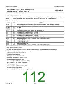
Table 100 Feedback buffers
OFFSET
NAME
BIT
TYPE
DESCRIPTION
144H
148H
FB_BUFFER1
FB_BUFFER2
31 to 0
31 to 0
RW
RW
feeds back audio data or stores status/control informations
feeds back audio data or stores status/control informations
Under control of the time slot list, a collected Dword is then stored into the input FIFO. The FIFO size is determined to
24 Dwords.
An audio sampling frequency of fs = 48 kHz and n = 16 time slots in a super frame results in a maximum data load for
the PCI from an audio capture DMA channel of 768 kbytes/s (the bit clock rate is 6144 kbit/s). That accounts for
approximately 13 Dwords per regular video line time. To generate audio output signals, a master read DMA control fills
the output FIFO. A Dword buffer is loaded from FIFO under control of the time slot list. The parallel-to-serial converter
takes a byte as programmed in the time slot list from one of the 8 buffer places; 4 in the Dword buffer and 4 in the
feedback buffer. The serial output is directed to one of the accessible SD pins. Positive and negative clock edge data
transmission is supported by optional BCLK inversion.
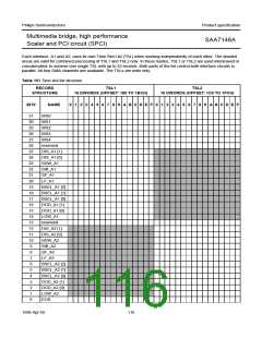
Each record in the time slot list describes, how the bytes appearing on the port, are mapped to the Dword wide DMA
channels, respectively to the feedback or input buffers. A time slot list record consists of 4 bytes. As up to 32 time slots
are supported, the time slot list is comprised of 16 Dwords of programming for each audio interface circuit A1 or A2 which
can be linked together.
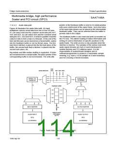
handbook, full pagewidth
IN
OUT
IN
OUT
TSL1
A1
TSL2
A2
FIFO1
FIFO1
FIFO2
FIFO2
DATAFLOW CONTROL
A1
DATAFLOW CONTROL
A2
WS
3 2
SD
3 2
WS
3 2
SD
3 2 1 0
4
1
0
4
1
0
4
1
0
4
I/O CONTROL
MGG282
WS4 WS3 WS2 WS1 WS0
SD4 SD3 SD2 SD1 SD0
Fig.41 Audio data path components.
1998 Apr 09
115

 NXP [ NXP ]