Philips Semiconductors
Product specification
Multimedia bridge, high performance
Scaler and PCI circuit (SPCI)
SAA7146A
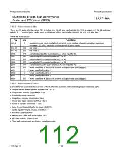
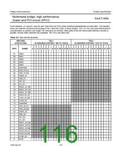
7.16.3 AUDIO INTERFACE PINS
There are 14 audio interface pins. SD1 is output only for A1 and input only for A2, SD4 is output only for A2 and input
only for A1. The other pins can be used by either one of the two interface circuits but only one at a time.
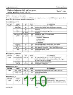
Table 99 Audio pin list
PIN
ACLK
I/O
FUNCTION
I
audio reference clock; multiple of serial bit clock, multiple of audio sampling; maximum
frequency 25 MHz; has to be provided even in slave mode
BCLK1
BCLK2
SD0
I/O
I/O
I/O
I/O
I/O
I/O
I/O
I/O
O
bit clock 1
bit clock 2
serial data output for audio interface A1 or input for A2
serial data I/O for audio interface A1 or A2
serial data I/O for audio interface A1 or A2
serial data I/O for audio interface A1 or A2
serial data input for audio interface A1 or output for A2
word select line 0, as input it is used as super frame sync (trigger)
word select output line 1
SD1
SD2
SD3
SD4
WS0
WS1
WS2
WS3
WS4
O
word select output line 2
O
word select output line 3
I/O
word select line 4, as input it is used as super frame sync (trigger)
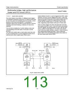
7.16.4 AUDIO INTERFACE CIRCUIT
Each of the two audio interface circuits of the SAA7146A consists of the following major functional parts:
• Output Dword (format) buffer (to load from FIFO)
• Output data selector (byte Mux 8 to 1)
• Parallel-to-serial converter
• Output pin selector (destination Mux)
• Serial data input selector (bit Mux 4 to 1)
• Serial-to-parallel converter (1 byte)
• Input Dword (format) buffer (to store into FIFO)
• Audio input FIFO and master write DMA
• Feedback (hand) buffer
• Master read DMA and audio output FIFO
• Bit clock selector or generator
• Time slot counter and word select signal generator.
1998 Apr 09
112

 NXP [ NXP ]