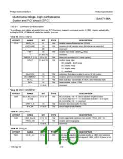
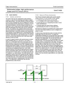
Philips Semiconductors
Product specification
Multimedia bridge, high performance
Scaler and PCI circuit (SPCI)
SAA7146A
pointer of the feedback buffer is reset to it’s initial position
with every start/restart of the super frame. Up to four bytes
of the input data stream can be placed in the intermediate
feedback buffer. They can be selected from the buffer to
provide data to the output.
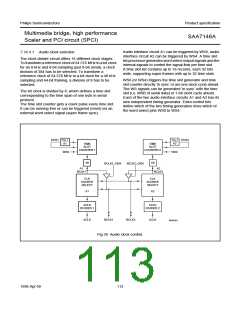
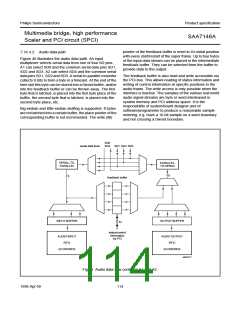
7.16.4.2 Audio data path
Figure 40 illustrates the audio data path. An input
multiplexer selects serial data from one of four SD pins.
A1 can select SD0 and the common serial data pins SD1,
SD2 and SD3. A2 can select SD4 and the common serial
data pins SD1, SD2 and SD3. A serial-to-parallel converter
collects 8 bits to form a byte in a timeslot. At the end of the
time slot this byte can be stored into a Dword buffer, and/or
into the feedback buffer or can be thrown away. The first
byte that is latched, is placed into the first byte place of the
buffer, the second byte that is latched, is placed into the
second byte place, etc.
The feedback buffer is also read and write accessible via
the PCI-bus. This allows reading of status information and
writing of control information at specific positions in the
audio frame. The write access is only possible when the
interface is inactive. The samples of the various real world
audio signal streams are byte or word interleaved in
system memory and PCI address space. It is the
responsibility of system/board designer and of
Big-endian and little-endian stuffing is supported. If bytes
are not latched into a certain buffer, the place pointer of the
corresponding buffer is not incremented. The write (fill)
software/programmer to produce a reasonable sample
ordering, e.g. have a 16-bit sample on a word boundary
and not crossing a Dword boundary.
SD0
SD4 SD1 SD2 SD3
handbook, full pagewidth
serial data lines
SERIAL-TO-
PARALLEL
PARALLEL-
TO-SERIAL
8
8
feedback buffer
INPUT BUFFER
OUTPUT BUFFER
32
status/control
information
via PCI
AUDIO INPUT
FIFO
AUDIO OUTPUT
FIFO
24 DWORDS
24 DWORDS
MGG277
Fig.40 Audio data flow control in A1 and A2.
1998 Apr 09
114

 NXP [ NXP ]