Philips Semiconductors
Product specification
Multimedia bridge, high performance
Scaler and PCI circuit (SPCI)
SAA7146A
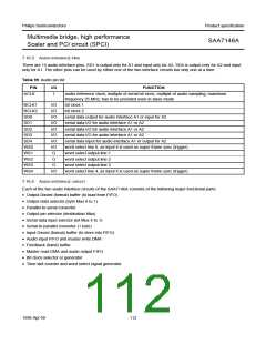
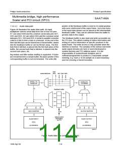
Audio interface circuit A1 can be triggered by WS0, audio
interface circuit A2 can be triggered by WS4. A time slot
list processor generates word select output signals and the
internal signals to control the signal flow per time slot.
A time slot list contains up to 16 records, each 32 bits
wide, supporting super frames with up to 32 time slots.
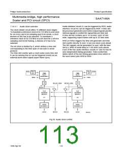
7.16.4.1 Audio clock selection
The clock divider circuit offers 16 different clock stages.
To transform a reference clock of 24.576 MHz to a bit clock
for an 8 kHz and 8-bit sampling (just 8-bit serial), a clock
division of 384 has to be selected. To transform a
reference clock of 24.576 MHz to a bit clock for a 48 kHz
sampling and 64-bit framing, a division of 8 has to be
selected.
WS0 (or WS4) triggers the time slot generator and time
slot counter directly ‘in sync’ or are one clock cycle ahead.
The WS signals can be generated ‘in sync’ with the time
slot (i.e. MSB of serial data) or 1-bit clock cycle ahead.
Each of the two audio interface circuits A1 and A2 has its
own independent timing generator. Extra control bits
define which of the two timing generators drive which of
the word select pins WS0 to WS4.
The bit clock is divided by 8, which defines a time slot
corresponding to the time span of one byte in serial
protocol.
The time slot counter gets a count pulse every time slot.
It can be running free or can be triggered (reset) via an
external word select signal (super frame sync).
handbook, full pagewidth
EOS1
TSL1
EOS2
TSL2
A2
A1
TIME
SLOT
TIME
SLOT
COUNTER 1
COUNTER 2
WS0
WS4
1/8
1/8
BCLK1_OEN
BCLK2_OEN
A1
A2
BCLK1
BCLK2
CLK
CLK
SOURCE
SELECT
SOURCE
SELECT
A1
A2
ACLK
ACLK
DIVIDER 1
DIVIDER 2
ACLK
BCLK1
BCLK2
ACLK
MGG281
Fig.39 Audio clock control.
1998 Apr 09
113

 NXP [ NXP ]