OXCB950
OXFORD SEMICONDUCTOR LTD.
7 INTERNAL 950 UART
The internal UART in the OXCB950 is an OX16C950 rev B specification high-performance serial port.
7.1 Operation – mode selection
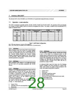
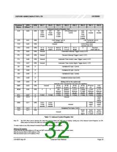
The UART is backward compatible with the 16C450, 16C550, 16C654 and 16C750 UARTs. The operation of the port depends
on a number of mode settings, which are referred to throughout this section. The modes, conditions and corresponding FIFO
depth are tabulated below:
UART Mode
FIFO
size
1
FCR[0]
Enhanced mode
FCR[5]
FIFOSEL
(EFR[4]=1)
(guarded with LCR[7] = 1)
Pin
450
0
X
X
X
550
Extended 550
650
16
1
1
1
1
1
0
0
1
0
1
0
X
X
1
0
128
128
128
128
1
X
0
750
1
950
X
X
Table 7: UART Mode Configuration
Note 1: 950 mode configuration is identical to 650 configuration
Note 2: The FIFOSEL pin is not available on the OXCB950 device. It is internally tied low.
7.1.1 450 Mode
After a hardware reset, bit 0 of the FIFO Control Register
7.1.4 650 Mode
(‘FCR’) is cleared, hence the UART is compatible with the
16C450. The transmitter and receiver FIFOs (referred to as
the ‘Transmit Holding Register’ and ‘Receiver Holding
Register’ respectively) have a depth of one. This is referred
to as ‘Byte mode’. When FCR[0] is cleared, all other mode
selection parameters are ignored.
The OXCB950 is compatible with the 16C650 when EFR[4]
is set, i.e. the device is in Enhanced mode. As 650
software drivers usually put the device in Enhanced mode,
running 650 drivers on the one of the UART channels will
result in 650 compatibility with 128 deep FIFOs, as long as
FCR[0] is set. Note that the 650 emulation mode of the
OXCB950 provides 128-deep FIFOs rather than the 32
provided by a legacy 16C650.
7.1.2 550 Mode
After a hardware reset, writing a 1 to FCR[0] will increase
the FIFO size to 16, providing compatibility with 16C550
devices.
In enhanced (650) mode the device has the following
features available over those provided by a generic 550.
(Note: some of these are similar to those provided in 750
mode, but enabled using different registers).
7.1.3 750 Mode
Writing a 1 to FCR[0] will increase the FIFO size to 16. In a
similar fashion to 16C750, the FIFO size can be further
increased to 128 by writing a 1 to FCR[5]. Note that access
to FCR[5] is protected by LCR[7]. i.e., to set FCR[5],
software should first set LCR[7] to temporarily remove the
guard. Once FCR[5] is set, the software should clear
LCR[7] for normal operation.
•
•
•
•
•
•
•
Deeper FIFOs
Sleep mode
Automatic in-band flow control
Special character detection
Infra-red “IrDA-format” transmit and receive mode
Transmit trigger levels
Optional clock prescaler
The 16C750 additional features are available as long as
the UART is not put into Enhanced mode; i.e. ensure
EFR[4] = ‘0’. These features are:
•
•
•
Deeper FIFOs
Automatic RTS/CTS out-of-band flow control
Sleep mode
DS-0033 Sep 05
External-Free Release
Page 28

 OXFORD [ OXFORD SEMICONDUCTOR ]