OXCB950
OXFORD SEMICONDUCTOR LTD.
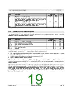
local configuration register GIS[20] to determine a
powerdown request. This powerdown filter stops the
UART and the MIO pins from issuing too many powerdown
interrupts whenever the UART and MIO pin activity is
intermittent.
Remaining with the UART, wake-up from the power state
D2 is configurable, and can be triggered by activity on any
combination of modem lines or the serial data input
(EXT_DATA_IN) line. In case of a wake up request from
the EXT_DATA_IN line when the device is in power-state
D2, the clock for that channel is turned on so serial data
framing can be maintained.
Upon a power down interrupt, the device driver can change
the power-state of the device as required. Note that the
power-state of the device is only changed by the device
driver and at no point will the OXCB950 change its own
power state. The powerdown interrupt merely informs the
device driver that this logical function is ready for power
down. Before placing the device into the lower power
states, the driver must provide the means for the function
to generate a ‘wakeup’ (power management) event.
For the case of the MIO pins, the state of the MIO pins that
results in wakeup requests is determined by the settings in
the local configuration register MIC. The wakeup behaviour
for these pins, unlike the UART, is not dependant upon the
powerstates D2 or D3. As soon as the correct logic is
invoked than a power management event (wakeup) is
asserted.
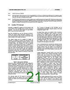
Whenever the device driver changes the power-state to
state D2 or D3, the device takes the following actions:
When the device issues a wake up request, the
PME_Status bit in the PCI power management registers
(PMCSR[15]) will be set. This is a sticky bit which will only
be cleared by writing a ‘1’ to it. While PME_En (PMCSR[8])
remains set, the PME_Status will continue to assert the
PME# pin or the CSYSCHG pin to inform the device driver
that a power management wake up event has occurred.
After a wake up event is signalled, the device driver is
expected to return the function to the D0 power-state.
•
•
The internal clock to internal UART is shut down.
Cardbus/PCI interrupts are disabled regardless of the
values contained in the GIS registers.
•
Access to I/O or Memory BARs.
However, access to the configuration space is still enabled.
The device driver can optionally assert/de-assert any of its
selected (design dependent) MIO pins to switch-off VCC,
disable other external clocks, or activate shut-down modes.
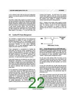
6.6.2 Power Reporting
The device can only issue a wakeup request (power
management event) if it is enabled by the PCI Power
Management Register PMCSR(8), the PME_En bit. PME#
assertion, the wakeup event for pci modes, and CSYSCHG
assertion, the wakeup event for cardbus modes, is
immediate and does not use the powerdown filter timer. It
operates even if the powerdown filter time is set to
disabled.
Power Management compliance expects the device to
report state dependant operating data such as power
consumed or heat dissipation. Typically, the data retuned
through the power management DATA register is a static
copy of the function’s worst case “DC characteristics” [PC
Card Standard].
When requested by the DATA_SELECT field, the DATA
register in the cardbus/PCI power Management Register
Block is required to report the state dependant data and
the DATA_SCALE field is required to return the scaling
factor to be used when interpretating the value of the data
register.
Like powerdown, wakeup requests can be generated by 3
sources: the internal UART and the 2 Multi_purpose MIO
pins. The means to generate wakeup events from these
sources will have been setup prior to placing the device
into the powerdown states D2 or D3.
The OXCB950 provides a mechanism for the manufacturer
to download values for the DATA_SCALE and DATA
registers for each of the 16 values of the DATA_SELECT
field. This allows manufacturers to incorporate power
consumption data into the power management registers
specific to their measurements and is available for both
cardbus and pci modes of the device. The facility to load
data into these areas is achieved by utilising the EEPROM
to download into the power management data zone.
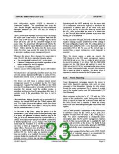
For the case of the UART, when the device is in the
powerstate D3, only activity on the RI line (the trailing edge
of a pulse) will generate a wakeup event as long as the
PME_En bit is set. When the device is in power-state D3, a
change in the state of any modem line which is enabled by
a 16C950-specific mask bit, or a change in the state of the
serial input line if enabled by a 16C950-specific mask bit
can issue a wake up request by asserting the wakeup
signal. After a hardware reset all of these mask bits are
cleared to enable wake up assertion from all modem lines
and the SIN line. As the wake up operation requires at
least one mask bit to be enabled, the device driver can for
example disable the masks with the exception of the Ring
Indicator, so only a modem ring can wake up the computer
Default values assigned to the DATA and DATA_SCALE
areas result in “unknown” values to be interpretated for
each of the 16 possible DATA_SELECT values.
DS-0033 Sep 05
External-Free Release
Page 23

 OXFORD [ OXFORD SEMICONDUCTOR ]