OXCB950
OXFORD SEMICONDUCTOR LTD.
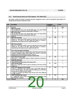
6.4.4 Global Interrupt Status and Control Register ‘GIS’ (Offset 0x0C)
This register controls the assertion of interrupts and power management events, as well as returning the internal status of all
interrupt sources and power management events.
Bits
Description
Read/Write
EEPROM
Reset
PCI
1:0
2
Reserved
-
R
0x0h
X
MIO0 Internal State.
-
R
This bit reflects the state of the internal MIO[0] signal. The internal MIO[0]
2
signal reflects the non-inverted or inverted state of MIO0 pin.
3
MIO1 Internal State
-
R
X
This bit reflects the state of the internal MIO[1] signal. The internal MIO[1]
2
reflects the non-inverted or inverted state of MIO1 pin.
17-4
18
Reserved
-
R
0
1
MIO0 Interrupt Enable
W
RW
When set (1), allows the pin MIO0 to assert an interrupt on the device’s INTA#
(CINT#) pin. The state of the MIO0 signal that causes an interrupt is
dependant upon the polarity set by the register fields MIC(1:0)
19
20
21
MIO1 Interrupt Enable
W
-
RW
R
1
X
0
When set (1), allows the pin MIO1 to assert an interrupt on the device’s INTA#
(CINT#) pin. The state of the MIO1 signal that causes an interrupt is
dependant upon the polarity set by the register fields MIC(3:2)
Power-down Internal Interrupt Status.
This is a sticky bit. When set, it indicates that a power-down request has been
recognised (validated), which would normally have asserted a powerdown
interrupt on the INTA# (CINT#) pin if GIS bit 21 was set.
Reading this bit clears the Internal Powerdown Interrupt Status.
Power-down interrupt enable.
W
RW
When set to ‘1’, a powerdown request is allowed to generate an interrupt on
the INTA#/ (CINT# ) pin.
. 1
22
23
UART interrupt status
-
R
0
1
This bit reflects the interrupt status of the internal UART.
UART Interrupt Enable.
W
R/W
When set (1), allows the UART to assert an interrupt on the device’s INTA#
3
(CINT# ) pin
24
UART Power Management Event Enable
W
R/W
0
A value of ‘1’ enables the UART ‘wakeup’ events to set the PME_Status bit in
the PCI PMCSR register, and hence assert the PME# (pci) or CSYSCHG
(cardbus) pin if this option has been enabled.
A value of ‘0’ prevents any wakeup events from the UART from setting the
PCI PME_Status bit.
25
UART Powerdown Filter Control
W
-
R/W
R
0
A ‘1’ enables the UART to invoke a powerdown request via the power down
filter (if the filter is enabled).
31:24 Reserved
00h
DS-0033 Sep 05
External-Free Release
Page 20

 OXFORD [ OXFORD SEMICONDUCTOR ]