OXCB950
OXFORD SEMICONDUCTOR LTD.
an I/O or Memory write to this bit in the local configuration
register or by using the optional EEPROM to download into
this area.
Function Event Register. The INTR field in the Function
Present State register will reflect the current (non-latched)
state of any internal interrupt requests and the INTR field in
the Function Force register is available to generate
software based interrupts for debug purposes.
Once these cardbus status registers are enabled, interrupts
will only be asserted on the device’s interrupt pin provided
that the INTR field is enabled in the Function Event Mask
Register (disabled by default) and the corresponding INTR
field in the Function Event Register has detected (latched)
a valid internal interrupt request. Once asserted, the
interrupt on the device’s interrupt pin can only be disabled
by either disabling the INTR field in the Function Event
Mask register or by writing a “1” to the INTR field of the
NOTE : Enabling of the cardbus status registers provides
additional controls to the interrupt generation/deassertion
logic. The interrupt controls in the local configuration
registers must nevertheless be enabled to detect the
interrupts from the device’s 3 interrupt sources in the first
place.
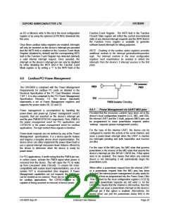
6.6 Cardbus/PCI Power Management
PCI connector
S
D
PME#
VDD
PME#
The OXCB950 is compliant with the Power Management
Requirements for cardbus PC cards as detailed in the
Electrical Specification of the PC Card Standard, release
7.0/7.1. It is also compliant to the PCI Power Management
Specification Revision 1.0. The device (function0)
implements a set of Power Management registers and
supports the power states D0, D2 and D3.
G
PME# Isolator Circuitry
6.6.1 Power Management via UART/ MIO pins
Power management is accomplished by handling the
power-down and power-up (“power management event”)
requests, that are asserted on the device’s interrupt pin
and the pins PME#/CSYSCHG respectively. Note, PME# is
the power management event for PCI applications and
CSYSCHG is the power management event for cardbus
applications. The logic behind these signals is identical.
Provided that the necessary controls have been set in the
device’s local configuration registers (LCC, MIC, and GIS),
the internal UART and the 2 multi_purpose (MIO) pins can
be programmed to issue powerdown requests and/or
‘wakeup’ requests (power management events).
For the case of the internal UART, the device can be
configured to monitor the activity of the serial channel, and
issue a power-down interrupt when the UART is inactive
(no interrupts pending and both transmitter and receiver
are idle).
Power-down requests are not defined by any of the Power
Management specifications. It is a device-specific feature
and requires a bespoke device driver implementation. The
device driver can either implement the power-down itself or
use a special interrupt and power-down features offered by
the device to determine when the device is ready for
power-down.
For the case of the MIO pins, the MIO state that governs
powerdown is the inverse of the MIO state that asserts the
device’s interrupt pin (the INTA# / CINT# line, if that option
were to be enabled). This means that when any external
device is not interrupting it will automatically begin the
powerdown cycle.
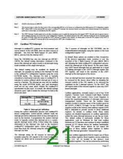
For PCI applications, it worth noting that the PME# pin can,
in certain cases, activate the PME# signal when power is
removed from the device. This will cause the PC to wake
up from Low-power state D3(cold). To ensure full cross-
compatibility with system board implementations, use of an
isolator FET is recommended (See diagram). If Power
Management capabilities are not required, the PME# pin
can be treated as no-connect. There are no such problems
for cardbus applications. The CSYSCHG line is not
capable of being asserted on removal of device power.
When either a powerdown request from the internal UART
or a powerdown request from the MIO pins has been
detected, the internal power management circuitry waits for
a period of time as programmed into the Power-Down Filter
Time (defined by the local configuration register LCC[7:5])
and if the powerdown requests are still valid i.e. for the
UART, this means that the channel is still inactive, then the
OXCB950 can issue a powerdown interrupt on the device’s
interrupt pin if this option is enabled. Alternatively, the
device driver can poll the powerdown status field in the
DS-0033 Sep 05
External-Free Release
Page 22

 OXFORD [ OXFORD SEMICONDUCTOR ]