OXCB950
OXFORD SEMICONDUCTOR LTD.
Bits
Description
Read/Write
EEPROM
Reset
PCI
6
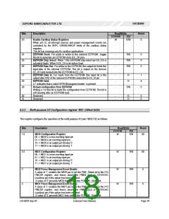
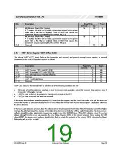
MIO0 Power Down Filter Control:
W
W
-
RW
RW
R
0
A ‘1’ enables the MIO0 pin to invoke a powerdown request via the power
down filter (if the filter is enabled). State of MIO0 that causes the
powerdown request is governed by the controls MIC[1:0).
MIO1 Power Down Filter Control:
7
0
A ‘1’ enables the MIO1 pin to invoke a powerdown request via the power
down filter (if the filter is enabled). State of MIO1 that causes the
powerdown request is governed by the controls MIC[3:2).
Reserved
31:8
00
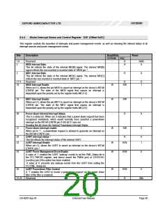
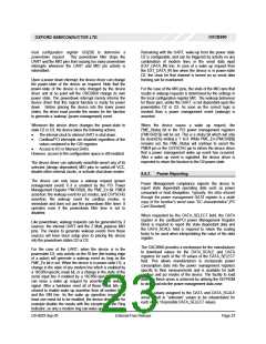
6.4.3 UART Mirror Register ‘UMR’ (Offset 0x08):
The internal UART’s FIFO levels (both on the transmitter and receiver) and general interrupt source register, is mirrored
(shadowed) in the local configuration registers as follows
Bits
Description
Read/Write
EEPROM
Reset
PCI
R
7:0
UART Receiver FIFO Level (RFL[7:0])
UART Transmitter FIFO Level (TFL[7:0])
UART Interrupt Source Register (ISR[5:0])
Reserved
-
-
-
-
-
-
00h
00h
01h
00h
1h
15:8
21:16
26:22
27
R
R
R
UART Good-Data Status
R
31:28
Reserved
R
0h
Good-Data status for the internal UART is set when all of the following conditions are met:
•
ISR reads a level0 (no-interrupt pending), a level 2a (receiver data available, a level 2b (receiver time-out) or a level 3
(transmitter THR empty) interrupt
•
•
LSR[7] is clear so there is no parity error, framing error or break in the FIFO
LSR[1] is clear so no over-run error has occurred
If the device driver software reads the receiver FIFO levels from this register, and the Good-Data status bit is set, the driver can
remove the number of bytes indicated by the FIFO level without the need to read the line status register. This feature enhances
the driver efficiency.
If the Good-Data status bit is not set, then the software driver should examine the ISR bits. If the ISR indicates a level 4 or higher
interrupt, the interrupt is due to a change in the state of modem lines or detection of flow control characters. The device driver-
software should then take appropriate measures as would in any other 550/950 driver. When ISR indicates a level 1 (receiver
status) interrupt then the driver can examine the Line Status Register (LSR) of the relevant channel. Since reading the LSR
clears LSR[7], the device driver-software should either flush or empty the contents of the receiver FIFO, otherwise the Good-
Data status will no longer be valid.
DS-0033 Sep 05
External-Free Release
Page 19

 OXFORD [ OXFORD SEMICONDUCTOR ]