OXCB950
OXFORD SEMICONDUCTOR LTD.
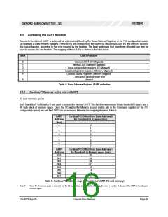
6.3 Accessing the UART function
Access to the internal UART is achieved (at addresses defined by the Base Address Registers in the PCI configuration space)
via standard I/O and memory mapping. These BARs are configured by the system to allocate blocks of I/O and memory space to
this logical function, according to the size required by the function. The base addresses that have been allocated can then be
used to access this uart function. The mapping of these BARs is shown in the table below.
BAR
UART Function
0
1
2
3
4
Internal UART (I/O Mapped)
Internal UART(Memory Mapped)
Local configuration registers (I/O Mapped)
Local configuration registers (Memory Mapped)
Cardbus Status Registers (Memory Mapped)
– relevant to cardbus mode only
Unused
5
Table 4: Base Address Register (BAR) definition
6.3.1 Cardbus/PCI access to the internal UART
IO and memory space
BAR 0 and BAR 1 of function 0 are used to access the internal UART. The function reserves an 8-byte block of I/O space and a
4K byte block of memory space. Once the I/O and/or the Memory access enable bits in the Command register (of the PCI
configuration space) are set, the UART can be accessed following the mapping shown in Table 5.
UART
Cardbus/PCI Offset from Base Address 0
for Function0 in IO space (hex)
Address
(hex)
0
1
0
1
2
2
3
3
4
4
5
5
6
6
7
7
UART
Address
000
001
002
003
004
005
006
007
Cardbus/PCI Offset from Base Address 1
for Function0 in Memory space (hex)
00
04
08
0C
10
14
18
1C
Table 5: Cardbus/PCI address map for the internal UART (I/O and memory)
Note 1:
Since 4K of memory space is reserved and the full bus address is not used for decoding, there are a number of aliases of the UART in the allocated
memory region
DS-0033 Sep 05
External-Free Release
Page 16

 OXFORD [ OXFORD SEMICONDUCTOR ]