NCL30486B
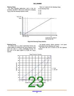
Dimming Clamp
For smart dimming applications, need to bias the
secondary−side MCU. This can be achieved by clamping
There are 4 options for the dimming clamp:
• No dimming clamp
• 1%
• 5%
• 8%
V
REFX
when the dimming setpoint is small.
V
REFX
(%)
100%
8%
5%
1%
0.01 0.05
1.0
0.08
Scaled dimming voltage or
dimming duty−ratio
Figure 66. Dimming Clamp Options
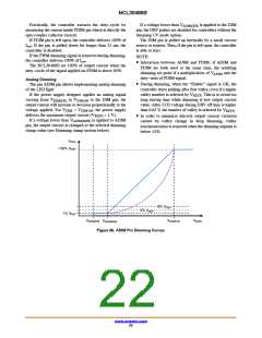
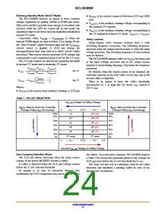
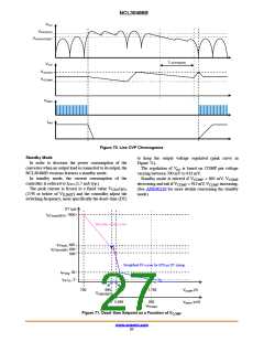
Dimming Curves
By default, there is a linear relationship between the
voltage applied on ADIM pin and V setpoint. In the
same way, there is a linear relationship between the
duty−ratio of the signal applied on PDIM and V
An internal memory allows selecting a root square
relationship between dimming and V
The square like curve is based on CIE 1931 lightness
formula.
.
REFX
REFX
REFX
setpoint.
Output Current vs. Dimming
100
90
80
70
60
50
40
30
20
10
0
linear
CIE 1931
0
0.1
0.2
0.3
0.4
0.5
0.6
0.7
0.8
0.9
1
Scaled Dimming Voltage or Dimming Duty Ratio
Figure 67. Dimming Curves
www.onsemi.com
23

 ONSEMI [ ONSEMI ]