NCL30486B
HV
vDD
vVS
CS
RLFF
I CS(offset)
KLFF
Rsense
Q_drv
+
25 ms
BO_NOK
Blanking
−
1 V / 0.9 V
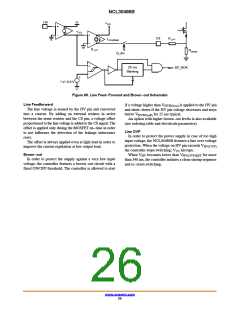
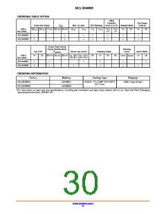
Figure 69. Line Feed−Forward and Brown−out Schematic
Line Feedforward
if a voltage higher than V
is applied to the HV pin
HVBO(on)
The line voltage is sensed by the HV pin and converted
into a current. By adding an external resistor in series
between the sense resistor and the CS pin, a voltage offset
proportional to the line voltage is added to the CS signal. The
offset is applied only during the MOSFET on−time in order
to not influence the detection of the leakage inductance
reset.
and shuts−down if the HV pin voltage decreases and stays
below V for 25 ms typical.
An option with higher brown−out levels is also available
HVBO(off)
(see ordering table and electricals parameters)
Line OVP
In order to protect the power supply in case of too high
input voltage, the NCL30486B features a line over voltage
The offset is always applied even at light load in order to
improve the current regulation at low output load.
protection. When the voltage on HV pin exceeds V
HV(OVP)
the controller stops switching; V hiccups.
CC
Brown−out
When V becomes lower than V
for more
HV
HV(OVP)RST
In order to protect the supply against a very low input
voltage, the controller features a brown−out circuit with a
fixed ON/OFF threshold. The controller is allowed to start
than 340 ms, the controller initiates a clean startup sequence
and re−starts switching.
www.onsemi.com
26

 ONSEMI [ ONSEMI ]