NCL30486B
2
Winding and Output Diode Short−Circuit Protection
In parallel to the cycle−by−cycle sensing of the CS pin,
Adding a minimum pad area of 215 mm of 35 mm copper
(1 oz) drops the R to around 120°C/W (no air flow, R
qJA
qJA
another comparator with a reduced LEB (t ) and a
measured at ADIM pin)
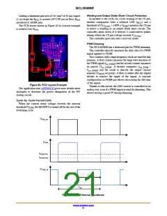
The PCB layout shown in Figure 63 is a layout example
to achieve low R
BCS
threshold of (V
= 140% x V
) monitors the CS pin
CS(stop)
ILIM
to detect a winding or an output diode short circuit. The
controller shuts down if it detects 4 consecutives pulses
.
qJA
during which the CS pin voltage exceeds V
CS(stop).
The controller goes into auto−recovery mode.
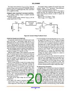
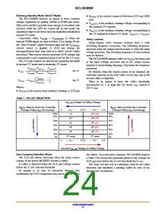
PWM Dimming
The NCL30486B has a dedicated pin for PWM dimming.
The controller directly measures the duty ratio of a PWM
signal applied to PDIM.
Two counters with a high frequency clock are used for this
purpose. A first counter measure the high state duration of
the PWM signal (t ) and the second counter measures
on_PDIM
its period (T
). A divider computes (t
/
sw_PDIM
on_PDIM
T
) and the result is directly the output current
sw_PDIM
setpoint (V
set point). A filter is added after the digital
REFX
divider to remove the ripple of the signal. A cascode
configuration on PDIM pin allows decreasing the fall time
of the signal.
Thanks to this circuit, the LED current is controlled in an
analog way, even if a PWM signal is used for dimming. This
allows having a good PF during dimming.
Figure 63. PCD Layout Example
The application note AND90120 gives more details about
strategies to decrease the power dissipation of the HV
startup circuit.
Cycle−by−Cycle Current Limit
When the current sense voltage exceeds the internal
threshold V , the MOSFET is turned off for the rest of the
ILIM
switching cycle.
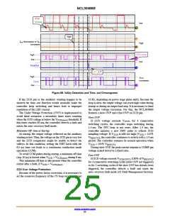
VDIM_sec
IPDIM
IPDIM(THD)
IPDIM(THR)
VPDIM_int
Ton
Tsw
Figure 64. PDIM Internal Waveforms
www.onsemi.com
21

 ONSEMI [ ONSEMI ]