NCL30486B
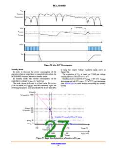
VHV
VHV(OVP)
VHV(OVP)RST
t LOVP(blank)
VCC
VCC(on)
VCC(off)
VDRV
Iout
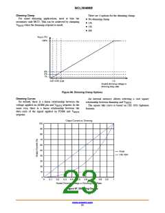
Figure 70. Line OVP Chronograms
Standby Mode
to keep the output voltage regulated (pink curve in
Figure 71).
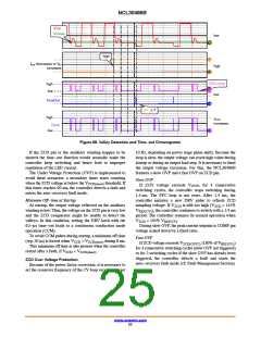
In order to decrease the power consumption of the
converter when no output load is connected to its output, the
NCL30486B versions features a standby mode.
In standby mode, the current consumption of the
controller is reduced to I
The peak current is frozen to a fixed value V
The regulation of V is based on COMP pin voltage
out
varying between 700 mV to 913 mV.
Standby mode is entered if V
< 895 mV, V
COMP
COMP
(1.7 mA typ.)
decreasing and exit if V
> 913 mV, V
increasing.
CC4
COMP
COMP
(See AND90120 for more details concerning the standby
mode)
CS(STBY)
(27% or below of V
switching frequency, more specifically the dead−time (DT)
) and the controller adjust the
ILIMIT
DT (ms)
t
, 1800
DT(max)SBY2
Standby mode curve
t
, 687
FFend1
t , 640
DT(min)SBY
560
Simplified FF curve for 675 ms DT clamp
t
, 35
FFchg
t
, 2
FF1LL
700
895
913
1.758
250
VCOMP (V)
V
CMP(SBY)
0 5.848
VREFX (mV)
V
FFstart
Figure 71. Dead−time Setpoint as a Function of VCOMP
www.onsemi.com
27

 ONSEMI [ ONSEMI ]