NCL30486B
VZCD
VZCD(th)
low
3
4
high
14
12
I
decreases or V
out
in
high
increases
ZCD comp
high
low
15
low
TimeOut
16
17
2nd , 3 rd
high
VVIN
increases
Clock
low
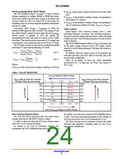
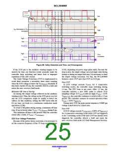
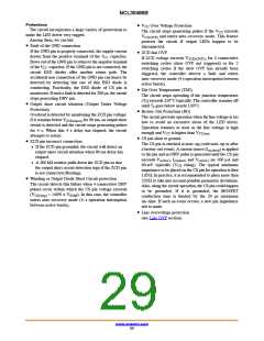
Figure 68. Valley Detection and Time−out Chronograms
If the ZCD pin or the auxiliary winding happen to be
shorted the time−out function would normally make the
controller keep switching and hence lead to improper
regulation of the LED current.
The Under Voltage Protection (UVP) is implemented to
avoid these scenarios: a secondary timer starts counting
10 Hz, depending on power stage phase shift). Because the
loop is slow, the output voltage can reach high value during
startup or during an output load step. It is necessary to limit
the output voltage excursion. For this, the NCL30486B
features a slow OVP and a fast OVP on ZCD pin.
Slow OVP
when the ZCD voltage is below the V
threshold. If
ZCD(short)
If ZCD voltage exceeds V
for 4 consecutive
OVP1
this timer reaches 90 ms, the controller detects a fault and
enters the auto−recovery fault mode.
switching cycles, the controller stops switching during
1.4 ms. The PFC loop is not reset. After 1.4 ms, the
controller initiates a new DRV pulse to refresh ZCD
Minimum Off−time at Startup
At startup, the output voltage reflected on the auxiliary
winding is low. Thus, the voltage on the ZCD pin is very low
and the ZCD comparator might be unable to detect the
valleys. In this condition, setting the DRV latch with the
6.5−ms time−out leads to a continuous conduction mode
operation (CCM).
sampling voltage. If V
is still too high (V
> 115%
ZCD
ZCD
V
), the controller continues to switch with a 1.4 ms
REF(CV)
period. The controller resumes its normal operation when
< 105% V
V
ZCD
.
REF(CV)
During slow OVP, the peak current setpoint is COMP pin
voltage scaled down by a fixed ratio.
To avoid CCM pulses during startup, a minimum off time
Fast OVP
If ZCD voltage exceeds V
for 4 consecutive switching cycles (slow OVP not triggered)
or for 2 switching cycles if the slow OVP has already been
triggered, the controller detects a fault and starts the
auto−recovery fault mode (cf: Fault Management Section)
(typ. 50 ms) is forced when V
< V
during 8 ms.
ZCD
ZCD(short)
(130% of V
)
ZCD(OVP2)
REF(CV)
This minimum off time is also present when the controller
restart after a fault, if V < V
.
ZCD(short)
ZCD
ZCD Over Voltage Protection
Because of the power factor correction, it is necessary to
set the crossover frequency of the CV loop very low (target
www.onsemi.com
25

 ONSEMI [ ONSEMI ]