TDF8544
NXP Semiconductors
I2C-bus controlled 4 50 W power amplifier
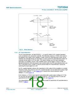
7.5.4 Distortion clip detection
If the amplifier output starts clipping at the supply voltage or ground, the output signal
becomes distorted. If the distortion per channel exceeds a selectable threshold (2 %, 5 %
or 10 %), either pin DIAG or pin STB is activated. To be able to detect if, for instance, the
front channels (channels 1 and 3) or rear channels (channels 2 and 4) are clipping, the
clip information per channel can be directed to either pin DIAG or pin STB.
It is possible to only have the clip information on the diagnostic pins by disabling the
temperature- and load information on pin DIAG. The temperature and load protection are
still functional but can only be read via the I2C-bus.
The clip detection level can be programmed via the I2C-bus. The clip information is
blocked below a supply voltage of 10 V to avoid false clip detection during engine start, or
can be programmed to operate at the low voltage detection level of 7.5 V or 6 V.
Since it is possible to have different amplifier gain settings between the front and rear
channels and there is only one clip reference current, the clip detect levels are only
accurate for the channels with the highest gain. In line driver mode the DC-output voltage
is 0.23VP and clip detection will still indicate a clip, but the levels will not be accurate.
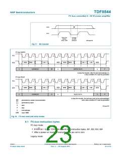
7.6 Line driver mode and low gain mode
The TDF8544 can be used as a line driver or as a low gain amplifier. In both situations, the
gain needs to be set to 16 dB via the I2C-bus (IB3[D5:D6] and can be independently set
for the front (channels 1 and 3) and rear (channels 2 and 4). The main difference between
line driver mode and low gain mode is the DC output voltage.
In line driver mode the TDF8544 is used to drive a separate amplifier or booster. In this
mode the DC output voltage is set to 0.23 battery voltage and is filtered with the
capacitor connected to pin SVR (same as VSVR). The reason not to set the DC output
voltage to half the battery voltage is to allow engine starts at a battery voltage as low as
6 V. The DC output voltage remains approximately 3 V during engine start. If the DC
output voltage is set to half the battery voltage, with an engine start the common mode
voltage will change quickly from 7 V to 3 V. This drives the input stage of the booster
below the ground level.
If the TDF8544 is used as a low gain amplifier in a booster, the DC output voltage is set to
half of the supply voltage to ensure maximum undistorted output power.
The line driver and low gain modes can be selected with I2C-bus bit IB4[D2].
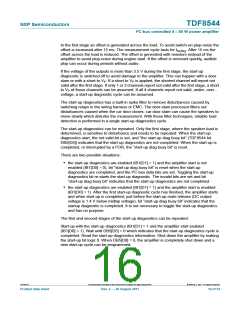
Table 7.
DC output voltage as a function of different gain settings
Channels 1 and 3
gain setting (dB)
Channels 2 and 4
gain setting (dB)
Line driver/low gain
mode IB4[D2][1]
All channels DC
output voltage (V)
26
16
26
16
16
26
26
16
16
16
X
0.5VP
0.5VP
0.5VP
0.5VP
0.23VP
X
X
low gain mode
line driver mode
[1] X = neither mode selected.
TDF8544
All information provided in this document is subject to legal disclaimers.
© NXP B.V. 2011. All rights reserved.
Product data sheet
Rev. 2 — 29 August 2011
20 of 54

 NXP [ NXP ]