TDF8544
NXP Semiconductors
I2C-bus controlled 4 50 W power amplifier
• All bits equal to zero define the setting, with the exception of bit IB1[D0] which is
ignored; see Table 9.
Table 9.
Bit
Instruction byte IB1
Description
D7
enable or disable clip detection below VP = 10 V
0 = disable clip detection below VP = 10 V
1 = enable clip detection below VP = 10 V
channel 3 clip information on pin DIAG or pin STB
0 = clip information on pin DIAG
1 = clip information on pin STB
D6
D5
D4
D3
D2
D1
D0
channel 1 clip information on pin DIAG or pin STB
0 = clip information on pin DIAG
1 = clip information on pin STB
channel 4 clip information on pin DIAG or pin STB
0 = clip information on pin DIAG
1 = clip information on pin STB
channel 2 clip information on pin DIAG or pin STB
0 = clip information on pin DIAG
1 = clip information on pin STB
enable or disable AC load detection
0 = AC load detection disabled
1 = AC load detection enabled
enable or disable start-up diagnostics
0 = start-up diagnostics disabled
1 = start-up diagnostics enabled
enable or disable amplifier start
0 = amplifier start not enabled
1 = amplifier start enabled
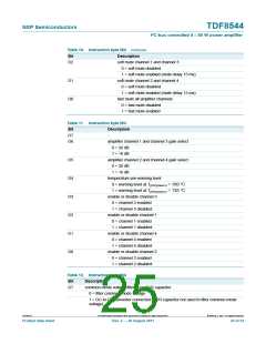
Table 10. Instruction byte IB2
Bit
Description
D7 and D6
clip detection level
00 = clip detection level 2 %
01 = clip detection level 5 %
10 = clip detection level 10 %
11 = clip detection level disabled
temperature information on pin DIAG
0 = temperature information on pin DIAG
1 = no temperature information on pin DIAG
load fault information (shorts) on pin DIAG
0 = load fault information on pin DIAG
1 = no load fault information on pin DIAG
-
D5
D4
D3
TDF8544
All information provided in this document is subject to legal disclaimers.
© NXP B.V. 2011. All rights reserved.
Product data sheet
Rev. 2 — 29 August 2011
24 of 54

 NXP [ NXP ]