TDF8544
NXP Semiconductors
I2C-bus controlled 4 50 W power amplifier
7.7 I2C-bus, legacy mode and address select pin
Pin ADSEL can select either of two amplifier modes: legacy mode or I2C-bus mode.
7.7.1 Address select (pin ADSEL)
The following amplifier functions are selected with pin ADSEL:
• Pin ADSEL shorted: (RADSEL < 470 ) legacy mode, no I2C-bus communication is
needed.
• Resistor connected between pin ADSEL and ground: where different I2C-bus
addresses can be selected with resistors.
• One I2C-bus address can be selected by either forcing a voltage on pin ADSEL or by
connecting a high ohmic resistor between pin ADSEL and VP.
To avoid address changes during low supply voltage, the address selected by the value of
resistor connected to pin ADSEL is latched at voltages below 6 V. The consequence is,
during start-up and after every power-on reset, the supply voltage must be above 6 V
otherwise the address is invalid.
7.7.2 Legacy mode (RADSEL < 470 )
The function of pin STB changes from off/operating to off/mute/operating and the amplifier
starts immediately when pin STB is put into mute or operating mode. Mute operating is
controlled via an internal timer (15 ms) to minimise mute-on plops. When pin STB is
switched directly from operating to off, first the hard mute is activated (switching to mute
within 400 s) and then the amplifier shuts down. To have a plop-free shut-down, first pin
STB should be switched to mute for 50 ms and then switched off.
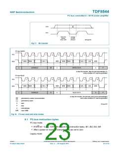
7.7.3 I2C-bus mode
If pin STB is LOW, the total quiescent current is low, and the I2C-bus lines are not loaded.
When pin STB is switched HIGH, the TDF8544 enters operating mode and performs a
POR which makes pin DIAG LOW. The TDF8544 starts when IB1[D0] = 1. Bit D0 also
resets the ‘power on reset occurred’ bit (DB2[D7]) and releases pin DIAG.
Soft mute and hard mute can be activated via the I2C-bus. Soft mute can be activated
independently for the front (channels 1 and 3) and rear (channels 2 and 4), and mutes the
audio in 15 ms. Hard mute activates the mute for all channels at the same time and mutes
the audio in 400 s. Unmuting after a hard mute will be a soft unmute of approximately
15 ms. When pin STB is switched to Off mode, and the amplifier has started, first the hard
mute is activated and then the amplifier shuts down. It is possible to fully mute the
amplifiers within 400 s by making pin STB LOW, for example during an engine start.
7.7.4 I2C-bus diagnostic bits read-out/cleared after read
The amplifier’s diagnostic information can be read via the I2C-bus. The I2C-bus bits are
set if a failure occurs and are reset by the I2C-bus read command (cleared after read).
When the failure is removed, the microcontroller knows the cause of the failure by reading
the I2C-bus. The consequence of this procedure is that old information is read during the
I2C-bus read. Most real information will be gathered within two consecutive read
commands.
TDF8544
All information provided in this document is subject to legal disclaimers.
© NXP B.V. 2011. All rights reserved.
Product data sheet
Rev. 2 — 29 August 2011
21 of 54

 NXP [ NXP ]