TDF8544
NXP Semiconductors
I2C-bus controlled 4 50 W power amplifier
V
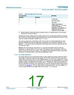
= (OUT+ - OUT-)
o
offset
threshold
time
reset, setting
disabled
1 second:
read → no offset,
DBx[D2] reset
V
= (OUT+ - OUT-)
o
offset
threshold
time
read →
set bit
1 second:
read → offset,
DBx[D2] set
001aam700
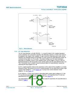
Fig 13. Offset detection
7.5.3 AC load detection
The AC load detection, set with IB1[D2] = 1, is used to detect if AC-coupled speakers
such as tweeters are connected correctly. The detection requires a 19 kHz sine wave to
be applied to the inputs of the amplifier. A high current AC-load detection mode can be
selected, for example during car assembly, or a low current AC-load detection mode, for
example during switch on of car radio. The output voltage over the load impedance
generates an amplifier current. If the amplifier peak current triggers 4 times a 580 mA
(peak) threshold (or 320 mA (peak) in low current mode), the AC-load detection bit is set.
The 4 ‘threshold cross’ counter is used to prevent false AC-load detection caused by
switching the input signal on or off.
An AC-coupled speaker reduces the impedance at the output of the amplifier in a certain
frequency band. The presence of an AC-coupled speaker can be determined using a high
current mode (IB4[D1] = 1, see Figure 14) or using a low current detection mode
(IB4[D1] = 0; see Figure 14.
If, for instance, a 19 kHz input signal is generated with a peak output voltage of 2 V the
I2C-bus bits are guaranteed to be set with a total AC + DC load less than 4 and are
guaranteed not set with a load of more than 9 ; see Figure 14.
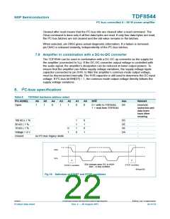
The interpretation of the line driver and amplifier mode DC load bit for AC load detection is
shown in Table 6.
TDF8544
All information provided in this document is subject to legal disclaimers.
© NXP B.V. 2011. All rights reserved.
Product data sheet
Rev. 2 — 29 August 2011
18 of 54

 NXP [ NXP ]