TDF8544
NXP Semiconductors
I2C-bus controlled 4 50 W power amplifier
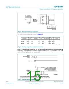
Table 6.
AC load detection
IB4[D4] = 1
DB1 to 4 [D4] (AC load bit)
No AC load detected
AC load detected
0
1
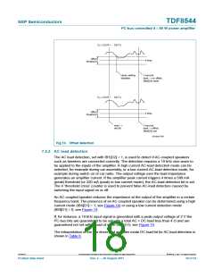
If IB1[D2] = 1 the AC-load detection measurement cycle is enabled, the peak counter is
reset and the measuring cycle starts. The AC-load detection is only performed after the
amplifier has completed its start-up cycle. Since the AC-load information in the I2C-bus
bits is combined with the start-up diagnostics, the AC-load information can be read when
IB4[D4] = 1. If IB4[D4] = 0, the stored AC-load bits cannot be read, but their values are
preserved.
001aam701
25
Z
L
(Ω)
20
no load detected,
l C-bus bits not set
15
10
5
2
trip level
load detected,
l C-bus bits set
2
0
0
2
4
6
V
(V)
oM
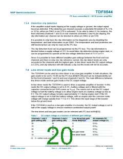
Fig 14. AC load impedance as a function of peak output voltage (high current AC-load
detection)
001aam702
50
Z
L
(W)
40
no load detected,
2
l C-bus bits not set
30
20
10
0
trip level
load detected,
2
l C-bus bits set
0
2
4
6
V
(V)
oM
Fig 15. AC load impedance as a function of peak output voltage (low current AC-load
detection)
TDF8544
All information provided in this document is subject to legal disclaimers.
© NXP B.V. 2011. All rights reserved.
Product data sheet
Rev. 2 — 29 August 2011
19 of 54

 NXP [ NXP ]