TDF8544
NXP Semiconductors
I2C-bus controlled 4 50 W power amplifier
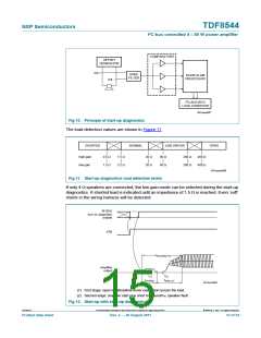
In the first stage an offset is generated across the load. To avoid switch-on plop-noise the
offset is increased after 15 ms. The measurement cycle lasts for tsudiag. After 15 ms the
offset across the load is reduced. The offset is generated with resistors instead of the
amplifier to avoid plop-noise during engine start. If the offset is removed quickly, audible
plop can occur during periods without audio.
If the voltage of the outputs is more than 3.5 V during the first stage, the start-up
diagnostic is switched off to avoid damage to the amplifier. This can happen with a door
slam or with a short to VP. If a short to VP is applied, the shorted channel will report not
valid after the first stage. If only 1 or 2 channels report not valid after the first stage, a short
to VP of those channels can be assumed. If all 4 channels report not valid, under- over -
voltage, a start-up diagnostic cycle can be assumed.
The start-up diagnostics has a built-in spike filter to remove disturbances caused by
switching relays in the wiring harness or EMC. The door-slam processor filters out
disturbances caused when the car door closes: car door-slam can cause the speakers to
move slowly which disturbs the measurement. With these filter techniques, reliable load
detection is performed in a single start-up diagnostics cycle.
The start-up diagnostics can be repeated. Only the first stage, where the speaker load is
determined, is sensitive to disturbance and needs to be repeated. When the start-up
diagnostics start, the not valid bit is set, and “the start-up diag busy bit” (TDF8544 bit
DB5[D5]) indicates that the start-up diagnostics are not completed. When the start-up is
completed, or interrupted by a POR, the “start-up diag busy bit” is reset.
There are two possible situations:
• the start-up diagnostics are enabled (IB1[D1] = 1) and the amplifier start is not
enabled (IB1[D0] = 0), bit “start-up diag busy bit” is reset when the start-up
diagnostics are completed, and the I2C-bus data bits are set. Toggling the start-up
diagnostics bit re-starts the start-up diagnostic. The invalid bits are set and bit
“start-up diag busy bit” indicates that the start-up diagnostics are not completed.
• the start-up diagnostics are enabled (IB1[D1] = 1) and the amplifier start is enabled
(IB1[D0] = 1). After the first start-up diagnostic cycle has finished, the amplifier starts
and when start-up is completed, just before the start-up mute release (DC output
voltage is 1.4 V below midtap voltage), bit “start-up diag busy bit” indicates that the
startup diagnostic is completed. It is not necessary to toggle the start-up diagnostics
and has no purpose.
The first and second stages of the start-up diagnostics can be repeated:
Start-up with the start-up diagnostics (IB1[D1] = 1 and the amplifier start enabled
(IB1[D0] = 1). Wait until DB5[D5] = 0 which indicates that the start-up diagnostics cycle is
completed. Read the start-up diagnostics information. Shut down the amplifier by making
the start-up bit logic 0. When DB5[D0] = 0, the amplifier is completely shut down and a
new start-up cycle can be programmed.
TDF8544
All information provided in this document is subject to legal disclaimers.
© NXP B.V. 2011. All rights reserved.
Product data sheet
Rev. 2 — 29 August 2011
16 of 54

 NXP [ NXP ]