A) Turn-on with current limit only: The current limit thresh-
old (ILIM) is determined by the current sense resistor (RS). If
the current limit threshold is less than the current defined by
the power limit threshold at maximum VDS the circuit operates
at the current limit threshold only during turn-on. Referring to
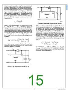
Figure 10a, as the load current reaches ILIM, the gate-to-
source voltage is controlled at VGSL to maintain the current at
ILIM. As the output voltage reaches its final value, (VDS ≊ 0V)
the drain current reduces to its normal operating value. The
time for the OUT pin voltage to transition from zero volts to
VSYS is equal to:
30086723
FIGURE 9. Load Draws Current During Turn-On
where CL is the load capacitance. For example, if VSYS = 12V,
CL = 1000 µF, and ILIM = 1A, tON calculates to 12 ms. The
maximum instantaneous power dissipated in the MOSFET is
12W. This calculation assumes the time from t1 to t2 in Figure
10a is small compared to tON, and the load does not draw any
current until after the output voltage has reached its final val-
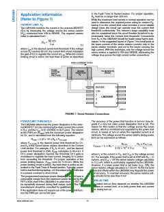
ue, and PGD switches high (Figure 8). If the load draws
current during the turn-on sequence (Figure 9), the turn-on
time is longer than the above calculation, and is approximate-
ly equal to:
B) Turn-on with power limit and current limit: The maxi-
mum allowed power dissipation in Q1 (PFET(LIM)) is defined by
the resistor at the PWR pin, and the current sense resistor
RS. See the Power Limit Threshold section. If the current limit
threshold (ILIM) is higher than the current defined by the power
limit threshold at maximum VDS (PFET(LIM)/VSYS) the circuit op-
erates initially in the power limit mode when the VDS of Q1 is
high, and then transitions to current limit mode as the current
increases to ILIM and VDS decreases. See Figure 10b. As-
suming the load (RL) is not connected during turn-on, the time
for the output voltage to reach its final value is approximately
equal to:
where RL is the load resistance. The Fault Timeout Period
must be set longer than tON to prevent a fault shutdown before
the turn-on sequence is complete.
For example, if VSYS = 12V, CL = 1000 µF, ILIM = 1A, and
PFET(LIM) = 10W, tON calculates to ≊12.2 ms, and the initial
current level (IP) is approximately 0.83A. The Fault Timeout
Period must be set longer than tON
.
30086722
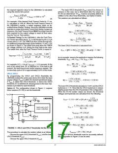
FIGURE 8. No Load Current During Turn-On
15
www.national.com

 NSC [ National Semiconductor ]