mΩ. Higher values may result in instability in the current limit
control loop.
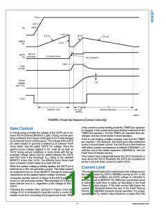
Fault Timer & Restart
When the current limit or power limit threshold is reached
during turn-on or as a result of a fault condition, the gate-to-
source voltage of Q1 is modulated to regulate the load current
and power dissipation in Q1. When either limiting function is
activated, an 80 µA fault timer current source charges the ex-
ternal capacitor (CT) at the TIMER pin as shown in Figure 5
(Fault Timeout Period). If the fault condition subsides during
the Fault Timeout Period before the TIMER pin reaches
1.72V, the LM25069 returns to the normal operating mode
and CT is discharged by the 2.5 µA current sink. If the TIMER
pin reaches 1.72V during the Fault Timeout Period, Q1 is
switched off by a 2 mA pull-down current at the GATE pin.
The subsequent restart procedure then depends on which
version of the LM25069 is in use.
Circuit Breaker
If the load current increases rapidly (e.g., the load is short-
circuited) the current in the sense resistor (RS) may exceed
the current limit threshold before the current limit control loop
is able to respond. If the current exceeds approximately twice
the current limit threshold (95 mV/RS), Q1 is quickly switched
off by the 260 mA pull-down current at the GATE pin, and a
Fault Timeout Period begins. When the voltage across RS
falls below 95 mV the 260 mA pull-down current at the GATE
pin is switched off, and the gate voltage of Q1 is then deter-
mined by the current limit or the power limit functions. If the
TIMER pin reaches 1.72V before the current limiting or power
limiting condition ceases, Q1 is switched off by the 2 mA pull-
down current at the GATE pin as described in the Fault Timer
& Restart section.
The LM25069-1 latches the GATE pin low at the end of the
Fault Timeout Period. CT is then discharged to ground by the
2.5 µA fault current sink. The GATE pin is held low by the 2
mA pull-down current until a power up sequence is externally
initiated by cycling the input voltage (VSYS), or momentarily
pulling the UVLO pin below its threshold with an open-collec-
tor or open-drain device as shown in Figure 4. The voltage at
the TIMER pin must be less than 0.3V for the restart proce-
dure to be effective.
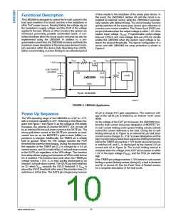
Power Limit
An important feature of the LM25069 is the MOSFET power
limiting. The Power Limit function can be used to maintain the
maximum power dissipation of MOSFET Q1 within the device
SOA rating. The LM25069 determines the power dissipation
in Q1 by monitoring its drain-source voltage (SENSE to OUT),
and the drain current through the sense resistor (VIN to
SENSE). The product of the current and voltage is compared
to the power limit threshold programmed by the resistor at the
PWR pin. If the power dissipation reaches the limiting thresh-
old, the GATE voltage is modulated to regulate the current in
Q1. While the power limiting circuit is active, the fault timer is
active as described in the Fault Timer & Restart section.
30086715
FIGURE 4. Latched Fault Restart Control
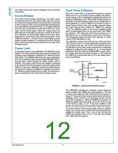
The LM25069-2 provides an automatic restart sequence
which consists of the TIMER pin cycling between 1.72V and
1V seven times after the Fault Timeout Period, as shown in
Figure 5. The period of each cycle is determined by the 80 µA
charging current, and the 2.5 µA discharge current, and the
value of the capacitor CT. When the TIMER pin reaches 0.3V
during the eighth high-to-low ramp, the 20 µA current source
at the GATE pin turns on Q1. If the fault condition is still
present, the Fault Timeout Period and the restart cycle repeat.
The Fault Timeout Period during restart cycles is approxi-
mately 18% shorter than the initial fault timeout period which
initiated the restart cycle. This is due to the fact that the
TIMER pin transitions from 0.3V to 1.72V after each restart
time, rather than from ground.
www.national.com
12

 NSC [ National Semiconductor ]