in the Fault Timer & Restart section. For proper operation,
RS must be no larger than 200 mΩ.
Application Information
(Refer to Figure 1)
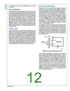
While the maximum load current in normal operation can be
used to determine the required power rating for resistor RS,
basing it on the current limit value provides a more reliable
design since the circuit can operate near the current limit
threshold continuously. The resistor’s surge capability must
also be considered since the circuit breaker threshold is ap-
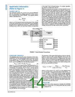
proximately twice the current limit threshold. Connections
from RS to the LM25069 should be made using Kelvin tech-
niques. In the suggested layout of Figure 7 the small pads at
the lower corners of the sense resistor connect only to the
sense resistor terminals, and not to the traces carrying the
high current. With this technique, only the voltage across the
sense resistor is applied to VIN and SENSE, eliminating the
voltage drop across the high current solder connections.
CURRENT LIMIT, RS
The LM25069 monitors the current in the external MOSFET
(Q1) by measuring the voltage across the sense resistor
(RS), connected from VIN to SENSE. The required resistor
value is calculated from:
(1)
where ILIM is the desired current limit threshold. If the voltage
across RS reaches 50 mV, the current limit circuit modulates
the gate of Q1 to regulate the current at ILIM. While the current
limiting circuit is active, the fault timer is active as described
30086719
FIGURE 7. Sense Resistor Connections
POWER LIMIT THRESHOLD
The accuracy of the power limit function at turn-on may de-
grade if a very low value power dissipation limit is set. The
reason for this caution is that the voltage across the sense
resistor, which is monitored and regulated by the power limit
circuit, is lowest at turn-on when the regulated current is at
minimum. The voltage across the sense resistor during power
limit can be expressed as follows:
The LM25069 determines the power dissipation in the exter-
nal MOSFET (Q1) by monitoring the drain current (the current
in RS), and the VDS of Q1 (SENSE to OUT pins). The resistor
at the PWR pin (RPWR) sets the maximum power dissipation
for Q1, and is calculated from the following equation:
RPWR = 2.32 x 10⁵ x RS x PFET(LIM)
(2)
where PFET(LIM) is the desired power limit threshold for Q1,
and RS is the current sense resistor described in the Current
Limit section. For example, if RS is 10 mΩ , and the desired
power limit threshold is 20W, RPWR calculates to 46.4 kΩ. If
Q1’s power dissipation reaches the threshold Q1’s gate is
modulated to regulate the load current, keeping Q1’s power
from exceeding the threshold. For proper operation of the
power limiting feature, RPWR must be ≤150 kΩ. While the
power limiting circuit is active, the fault timer is active as de-
scribed in the Fault Timer & Restart section. Typically, power
limit is reached during startup, or if the output voltage falls due
to a severe overload or short circuit.
where IL is the current in RS, and VDS is the voltage across
Q1. For example, if the power limit is set at 20W with RS = 10
mohms, and VDS = 15V the sense resistor voltage calculates
to 13.3 mV, which is comfortably regulated by the LM25069.
However, if a lower power limit is set lower (e.g., 2W), the
sense resistor voltage calculates to 1.33 mV. At this low level
noise and offsets within the LM25069 may degrade the power
limit accuracy. To maintain accuracy, the sense resistor volt-
age should not be less than 5 mV.
The programmed maximum power dissipation should have a
reasonable margin from the maximum power defined by the
FET's SOA chart if the LM25069-2 is used since the FET will
be repeatedly stressed during fault restart cycles. The FET
manufacturer should be consulted for guidelines.
TURN-ON TIME
The output turn-on time depends on whether the LM25069
operates in current limit, or in both power limit and current
limit, during turn-on.
If the application does not require use of the power limit func-
tion the PWR pin can be left open.
www.national.com
14

 NSC [ National Semiconductor ]