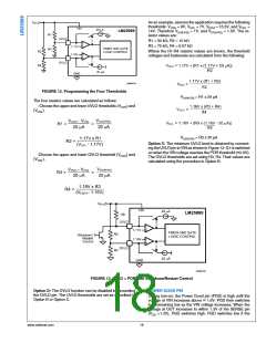
As an example, assume the application requires the following
thresholds: VUVH = 8V, VUVL = 7V, VOVH = 15.5V, and VOVL
=
14V. Therefore VUV(HYS) = 1V, and VOV(HYS) = 1.5V. The re-
sistor values are:
R1 = 50 kΩ, R2 = 10 kΩ
R3 = 75 kΩ, R4 = 6.07 kΩ
Where the R1-R4 resistor values are known, the threshold
voltages and hysteresis are calculated from the following:
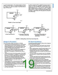
30086741
FIGURE 12. Programming the Four Thresholds
VUV(HYS) = R1 x 20 µA
The four resistor values are calculated as follows:
- Choose the upper and lower UVLO thresholds (VUVH) and
(VUVL).
VOV(HYS) = R3 x 20 µA
Option C: The minimum UVLO level is obtained by connect-
ing the UVLO pin to VIN as shown in Figure 13. Q1 is switched
on when the VIN voltage reaches the POR threshold (≊2.6V).
The OVLO thresholds are set using R3, R4. Their values are
calculated using the procedure in Option B.
-Choose the upper and lower OVLO threshold (VOVH) and
(VOVL).
30086750
FIGURE 13. UVLO = POR with Shutdown/Restart Control
Option D: The OVLO function can be disabled by grounding
the OVLO pin. The UVLO thresholds are set as described in
Option B or Option C.
POWER GOOD PIN
During turn-on, the Power Good pin (PGD) is high until the
voltage at VIN increases above ≊ 1.6V. PGD then switches
low, remaining low as the VIN voltage increases. When the
voltage at OUT increases to within 1.3V of the SENSE pin
(VDS <1.3V), PGD switches high. PGD switches low if the
www.national.com
18

 NSC [ National Semiconductor ]