the required capacitor value for the LM25069-2 is calculated
using this shorter time period:
- The lower OVLO threshold (VOVL) cannot be chosen in
advance in this case, but is determined after the values for
R1-R3 are determined. If VOVL must be accurately defined in
addition to the other three thresholds, see Option B below.
The resistors are calculated as follows:
(4)
For example, if the desired Fault Timeout Period is 17 ms,
CT calculates to 0.96 µF. When the Fault Timeout Period of
the LM25069-2 expires, a restart sequence starts as de-
scribed below (Restart Timiing). Since the LM25069 normally
operates in power limit and/or current limit during a power-up
sequence, the Fault Timeout Period MUST be longer than the
time required for the output voltage to reach its final value.
See the Turn-on Time section
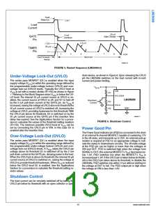
C) Restart Timing For the LM25069-2, after the Fault Time-
out Period described above, CT is discharged by the 2.5 µA
current sink to 1.0V. The TIMER pin then cycles through sev-
en additional charge/discharge cycles between 1V and 1.72V
as shown in Figure 5. The restart time ends when the TIMER
pin voltage reaches 0.3V during the final high-to-low ramp.
The restart time, after the Fault Timeout Period, is equal to:
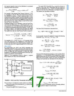
The lower OVLO threshold is calculated from:
As an example, assume the application requires the following
thresholds: VUVH = 8V, VUVL = 7V, VOVH = 15V.
= CT x 2.65 x 10⁶
For example, if CT = 0.8 µF, tRESTART = 2.12 seconds. At the
end of the restart time, Q1 is switched on. If the fault is still
present, the fault timeout and restart sequence repeats. The
on-time duty cycle of Q1 is approximately 0.67% in this mode.
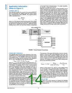
UVLO, OVLO
By programming the UVLO and OVLO thresholds the
LM25069 enables the series pass device (Q1) when the input
supply voltage (VSYS) is within the desired operational range.
If VSYS is below the UVLO threshold, or above the OVLO
threshold, Q1 is switched off, denying power to the load. Hys-
teresis is provided for each threshold.
The lower OVLO threshold calculates to 13.9V, and the OVLO
hysteresis is 1.1V. Note that the OVLO hysteresis is always
slightly greater than the UVLO hysteresis in this configuration.
When the R1-R3 resistor values are known, the threshold
voltages and hysteresis are calculated from the following:
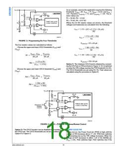
Option A: The configuration shown in Figure 11 requires
three resistors (R1-R3) to set the thresholds.
VUV(HYS) = R1 x 20 µA
30086729
FIGURE 11. UVLO and OVLO Thresholds Set By R1-R3
VOV(HYS) = (R1 + R2) x 20 µA
The procedure to calculate the resistor values is as follows:
- Choose the upper UVLO threshold (VUVH), and the lower
UVLO threshold (VUVL).
Option B: If all four thresholds must be accurately defined,
the configuration in Figure 12 can be used.
- Choose the upper OVLO threshold (VOVH).
17
www.national.com

 NSC [ National Semiconductor ]