MT9092
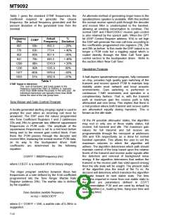
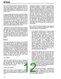
Table 1 gives the standard DTMF frequencies, the
coefficient required to generate the closest
frequency, the actual frequency generated and the
percent deviation of the generated tone from the
nominal.
An alternate method of generating ringer tones to the
speakerphone speaker is available. With this method
the normal receive speech path through the decoder
and receive filter is uninterrupted to the handset,
allowing an existing conversation to continue. The
normal DSP and Filter/CODEC receive gain control
is also retained by the speech path. When the OPT
bit (DSP Control Register address 1Eh) is set high
the DSP will generate the new call tone according to
the coefficients programmed into registers 23h, 24h
and 26h as before. In this mode the DSP output is no
longer a PCM code but a toggling signal which is
routed directly through the New Call Tone gain
control section to the loudspeaker driver. Refer to
the section titled ‘New Call Tone’.
Frequency
(Hz)
Actual
%
COEF
Frequency Deviation
697
770
59h
63h
6Dh
79h
9Bh
ABh
BDh
D1h
695.3
773.4
-.20%
+.40%
-.05%
+.46%
+.20%
.00%
852
851.6
941
945.3
1209
1336
1477
1633
1210.9
1335.9
1476.6
1632.8
Handsfree Program
-.03%
-.01%
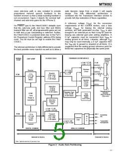
A half-duplex speakerphone program, fully contained
on chip, provides high quality gain switching of the
transmit and receive speech PCM to maintain loop
stability under most network and local acoustic
environments. Gain switching is performed in
continuous 1.5dB increments and operates in a
complimentary fashion. That is, with the transmit
path at maximum gain the receive path is fully
attenuated and vice versa. This implies that there is
a mid position where both transmit and receive paths
are attenuated equally during transition. This is
known as the idle state.
Table 1
DTMF Signal to distortion:
The sum of harmonic and noise power in the
frequency band from 50Hz to 3500Hz is typically
more than 30dB below the power in the tone pair. All
individual harmonics are typically more than 40dB
below the level of the low group tone.
Tone Ringer and Gain Control Program
A locally generated alerting (ringing) signal is used to
prompt the user when an incoming call must be
answered. The DSP uses the values programmed
into Tone Coefficient Registers 1 and 2 (addresses
23h and 24h) to generate two different squarewave
frequencies in PCM code. The amplitude of the
squarewave frequencies is set to a mid level before
being sent to the receive gain control block. From
there the PCM passes through the decoder and
receive filter, replacing the normal receive PCM data,
on its way to the loudspeaker driver. Both
coefficients are determined by the following
equation:
Of the 64 possible attenuator states, the algorithm
may rest in only one of three stable states; full
receive, full transmit and idle. The maximum gain
values for full transmit and full receive are
programmable through the microport at addresses
20h and 1Dh respectively, as is done for normal
handset operation. This allows the user to set the
maximum volumes to which the algorithm will
adhere. The algorithm determines which path should
maintain control of the loop based upon the relative
levels of the transmit and receive audio signals after
the detection and removal of background noise
energy. If the algorithm determines that neither the
transmit or the receive path has valid speech energy
then the idle state will be sought. The present state
of the algorithm plus the result of the Tx vs. Rx
decision will determine which transition the algorithm
will take toward its next stable state. The time
durations required to move from one stable state to
the next are parameters defined in CCITT
Recommendation P.34 and are used by default by
this algorithm (i.e., build-up time, hang-over time and
switching time).
COEFF = 8000/Frequency (Hz)
where COEFF is a rounded off 8 bit binary integer.
The ringer program switches between these two
frequencies at a rate defined by the 8-bit coefficient
programmed into the Tone Ringer Warble Rate
Register (address 26h). The warble rate is defined
by the equation:
Tone duration (warble frequency
in Hz) = 500/COEFF
where 0 < COEFF < 256, a warble rate of 5-20Hz is
suggested.
7-10

 MITEL [ MITEL NETWORKS CORPORATION ]