MT9092
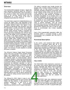
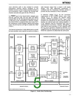
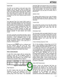
voice side-tone path is also included to provide
proportional transmit speech feedback to the
handset receiver so that a dead sounding handset is
not encountered. Figure 3 depicts the nominal half-
channel and side-tone gains for the HPhone-II.
wide dynamic range from a single 5 volt supply
design. This fully differential architecture is
continued into the Transducer Interface section to
provide full chip realization of these capabilites.
A reference voltage (V ), for the conversion
Ref
On PWRST (pin 6) the Filter/CODEC defaults such
that the side-tone path, dial tone filter and 400Hz
transmit filter are off, all programmable gains are set
to 0dB and µ-Law companding is selected. Further,
the Filter/CODEC is powered down due to the PuFC
bit (Transducer Control Register, address 0Eh) being
reset. This bit must be set high to enable the Filter/
CODEC.
requirements of the CODER section, and a bias
voltage (V
), for biasing the internal analog
Bias
sections, are both generated on-chip. V
is also
Bias
brought to an external pin so that it may be used for
biasing any external gain plan setting amplifiers. A
0.1µF capacitor must be connected from V
to
Bias
analog ground at all times. Likewise, although V
Ref
may only be used internally, a 0.1µF capacitor from
the V pin to ground is required at all times. It is
Ref
suggested that the analog ground reference point for
these two capacitors be physically the same point.
The internal architecture is fully differential to provide
the best possible noise rejection as well as to allow a
TRANSDUCER INTERFACE
SERIAL
PORT
FILTER/CODEC
Handset
Receiver
(150Ω)
DSP GAIN*
µ-Law –6.3 dB
Α-Law –3.7 dB
-6 dB
HSPKR+
Receiver
Driver
75
Receive
HSPKR–
-6 dB
Receive
Filter Gain
0 to –7 dB
(1 dB steps)
–72 to
+22.5 dB
(1.5dB
PCM
75
steps)
SPKR+
SPKR–
Speaker
Phone
Driver
0.2dB*
Side-tone
–9.96 to
+9.96dB
(3.32 dB steps)
Speakerphone
Speaker
(40Ω nominal)
(32Ω min)
Speaker Gain
0 to –24 dB
(8 dB steps)
DTMF,
Tone
Tone
Ringer
(input
Ringer &
Handsfree
from DSP)
Side-tone
Nominal
Gain
µ-Law –11 dB
Α-Law –18.8 dB
PCM
Transmit
Filter Gain
0 to +7dB
(1 dB steps)
MIC+
MIC–
–72 to
+22.5 dB
(1.5dB
steps)
Handsfree
mic
M
U
X
Transmit
Gain
M+
M–
µ-Law 6.1dB
Α-Law 15.4dB
Transmitter
microphone
Transmit
DIGITAL DOMAIN
ANALOG DOMAIN
Internal to Device
External to Device
Note: *gain the same for A-Law and µ−Law
Figure 3 - Audio Gain Partitioning
7-7

 MITEL [ MITEL NETWORKS CORPORATION ]