MT9092
packet) and FA (frame abort) are set before writing
the last packet byte to the Tx FIFO. The act of
loading the last packet byte will then automatically
reset the EOP and FA bits. Tx FIFO bytes are
continuously transmitted until the FIFO is empty, by
which time an EOP or FA tag should have been
encountered by the transmitter.
Command/Address byte which indicates a microport
read of address 07h. Since all interrupts are
generated by the occurrence of an HDLC event (i.e.,
a transition), this register informs that an event has
occurred but does not guarantee that it is still valid.
To determine current validity the HDLC Status
Register (address 04h) should be read. Due to the
asynchronous nature of the interrupts an interrupt
occurring during a read of the Interrupt Status
register will be held until the read cycle is over,
unless it is an interrupt which is already valid.
After the last bit of the EOP byte has been
transmitted a 16 bit FCS is sent followed by a closing
flag. When multiple packets of data are loaded into
the Tx FIFO only one flag is sent between packets.
There are three interrupts associated with the
transmitter.
When the transmitter encounters a byte tagged FA
then a frame abort sequence is sent instead of the
tagged byte. All bytes previous to but not including
the tagged byte are sent.
TEOP
TxFL
Transmit End Of Packet:
Set when the transmitter has finished
sending the closing flag of a packet or
after an abort sequence has been
completed.
The transmitter returns to its programmed wait state
after concluding the transmission of EOP or FA if the
Tx FIFO is empty.
Transmit FIFO Low:
Transmit FIFO Status
Set when a transition from 5 to 4 bytes
in the Tx FIFO has occurred. This is an
early warning to the microprocessor
that the FIFO is emptying and should
be serviced before it empties
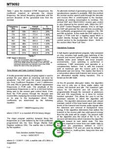
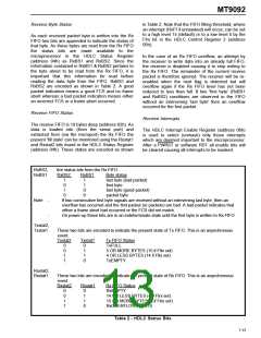
The transmit FIFO is 19 bytes deep (address 02h).
As data is loaded into (from the microport) and
extracted from (via the serial port) the Tx FIFO the
present 'fill state' can be monitored using the Txstat1
and Txstat2 bits found in the HDLC Status Register
(address 04h). These states are encoded as shown
in Table 2. Note that the FIFO emptying threshold,
where an interrupt (TxFL if unmasked) will occur, can
be set to a low level 4 (default) or to a high level 14
by the Fltx bit in the HDLC Control Register 2
(address 05h).
completely;
a
condition which will
result in a transmit underrun unless an
EOP or FA byte has been written to the
FIFO. By setting the Fltx bit (address
05h) high the FIFO emptying condition
will occur at the transition from 15 to 14
bytes. This will allow the microport
more time to react to this interrupt
condition.
A Tx FIFO underrun occurs if the Tx FIFO empties
without the occurrence of an EOP or FA tagged byte.
A frame abort sequence is automatically transmitted
under this condition.
Txunder Transmit underrun:
Set when the Tx FIFO empties without
the occurrence of an EOP or FA
tagged byte. A frame abort sequence
is automatically transmitted under this
condition. Note that this register bit
position is shared with the frame abort
(FA) interrupt (see receive interrupts).
For this bit to reflect Txunder the Intsel
bit in Control Register 2 (address 05h)
must be set high.
Transmit Interrupts
The HDLC Interrupt Enable Register (address 06h)
is used to select (unmask) only those interrupts
which are deemed important to the microprocessor.
After a PWRST or software RST all enable bits will
be cleared causing all interrupts to be masked.
Disabling, Reset, Transparent Operation and CRC
All selected interrupt events will cause the IRQ pin to
become active. Unselected interrupt events will not
cause IRQ to become active however, the event will
still be represented by the appropriate bit in the
HDLC Interrupt Status Register (address 07h). This
register must be read after receiving an IRQ or may
be polled at any time. The IRQ output pin is reset
coincident with the first SCLK falling edge following a
Disabling the transmitter via the HTxEn bit will occur
after the current packet is completely transmitted.
The status and Interrupt registers may still be read
and the Tx FIFO and control registers written while
the transmitter is disabled.
7-13

 MITEL [ MITEL NETWORKS CORPORATION ]