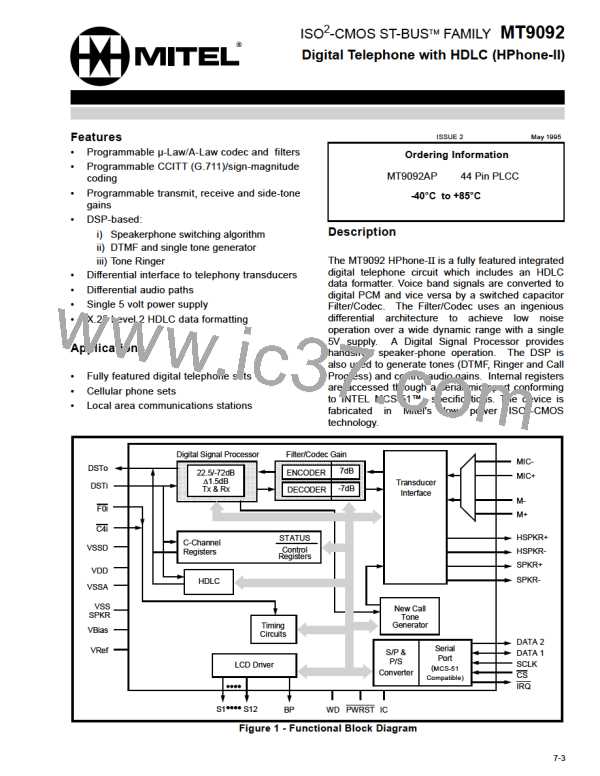
MT9092
The Tx FIFO may be reset by setting the Txfrst bit in
the HDLC Control Register 2 (address 05h). The
HDLC Status Register will identify the Tx FIFO as
being empty although the actual data in the FIFO will
not be reset. Txfrst will be cleared by the next write
to the Tx FIFO.
If address recognition is required, Receive Address
Recognition Registers 1 and/or 2 (addresses 00h
and 01h respectively) are loaded with the desired
address comparison information, the Adrec bit is set
high and A1EN and A2EN are set as required. Bit 0
(A1EN and A2EN) of both recognition registers is
used as an enable for that byte. When either of these
bits are low their respective address mask
information is ignored. In this way either or both of
the first two received bytes can be compared to the
expected mask values. Only those packets passing
the appropriate comparison test will be loaded into
the Rx FIFO. The appropriate comparison test
(single/dual byte address, All-call) is defined by the
logic state of bit 0 of the first byte received after the
opening flag.
Transparent data may be sent by setting the TRANS
bit (address 03h) high. The transmitter will no longer
generate the flag, abort and idle sequences, nor will
it insert zeros and append the FCS. Data will still be
transmitted LSB first. If there is no data in the Tx
FIFO or the Tx FIFO empties the last byte
transmitted will be repetitively sent until new data is
presented to the FIFO. It will take typically two ST-
BUS frames, after writing TRANS, before this mode
begins. Note that CH EN must also be set.
0
Bit 0 of the first received address byte (address
extension bit) is monitored to determine if a single or
dual byte address is being received.
Transmission of the FCS field CRC may be inhibited
using the Tcrci (Transmit Crc Inhibit) bit at address
05h. While this bit is set the opening flag followed by
the data fields and closing flag is transmitted,
including zero insertion, but the calculated CRC is
not. This allows the processor to insert the CRC as
part of the data field. This usage is for V.120 terminal
adaptation for synchronous protocol sensitive UI
frames.
1. If the address extension bit is 1 then a single
byte address is being received. If A1EN is high
the stored bit mask (Adr11 - Adr16 and
sometimes Adr10) is compared to the received
first address byte. Any packet failing this
address comparison will not be stored in the Rx
FIFO except for the All-call condition. A1EN
must be set high for a single-byte All-call
(11111111) address to be recognized. The
second mask byte is ignored. Seven bits of
address comparison may be realized for single
byte recognition by setting the SEVEN bit
(address 05h) high. This mode will then include
Adr10 as part of the mask information. The first
received byte must also have bit 0 set to a 1
indicating single byte addressing.
Receiver
Following initialization and enabling, via the HRxEN
bit at address 03h, the receiver begins clocking in
serial data checking for flags (0111 1110), go-aheads
(0111 1111 0), and idle channel states (at least fifteen
contiguous ones). Upon detecting a flag the receiver
synchronizes itself to the data stream and begins
calculating the CRC. If the packet length, between
the flags and after zero deletion, is less than 25 bits
the packet is ignored and nothing is written to the Rx
FIFO. If the packet length, after zero deletion, is
between 25 and 31 bits a last byte, bad packet
indication is written into the Rx FIFO.
2. If the address extension bit is 0 then a two byte
address is being received and the six most
significant bits of the first received byte are
compared. The seven most significant bits of the
second received byte are compared (Adr20 -
Adr26, note A2EN must be set high also). Any
packet failing this address comparison will not
be stored in the Rx FIFO. An All-call condition
(1111111x) is also monitored for in the second
received address byte and, if found, the first and
second byte masks are ignored (not compared
with the mask byte). Packets addressed with All-
call are written into the Rx FIFO.
Idle Channel
When the receiver detects at least 15 contiguous
ones it declares an idle channel condition exists and
sets the IdleChan bit in the HDLC status register
high (address 04h). This bit remains set until the
received condition changes.
Address Recognition
In CCITT Q.921 parlance the Adr11 - Adr16 bits are
defined as Sapi0 - Sapi5 (Service Access Point
Identifier n). Adr10 is defined as C/R (Command/
Response). Adr20 - Adr26 are defined as Tei0 - Tei6
(Terminal Endpoint Identifier n).
When Adrec (HDLC Control Register 1, address
03h) is low all valid received packets, regardless of
the address field information, are loaded into the Rx
FIFO.
7-14

 MITEL [ MITEL NETWORKS CORPORATION ]