MT9092
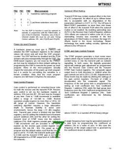
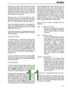
PS2 PS1
PS0
Micro-program
Optional Offset Nulling
1
0
0
handsfree switching program
Transmit PCM may contain residual offset in the form
of a DC component. An offset of up to ±fifteen linear
bits is acceptable with no degradation of the
parameters defined in CCITT G.714. The HPhone-II
filter/CODEC guarantees no more than ±ten linear
bits of offset in the transmit PCM when the autonull
routine is not enabled. By enabling autonulling (see
AUTO in the Receive Gain Control Register, address
1Dh) offsets are reduced to within ±one bit of zero.
Autonulling circuitry was essential in the first
generations of Filter/Codecs to remove the large DC
offsets found in the linear technology. Newer
technology has made nulling circuitry optional as
offered in the HPhone-II.
1
1
1
0
1
1
1
0
1
Last three selections reserved
Note:
For the DSP to function it must be selected to
operate, in conjunction with the Filter/Codec, in
one of the B-Channels. Therefore, one of the B-
Channel enable bits must be set (see Timing
Control, address 15h : bits CH EN and CH EN).
2
3
Power Up reset Program
A hardware power-up reset (pin 6, PWRST) will
initialize the DSP hardware registers to the default
values (all zeros) and will reset the DSP program
counter. The DSP will then be disabled and the PCM
streams will pass transparently through the DSP. The
RAM-based registers are not reset by the PWRST
pin but may be initialized to their default settings by
programming the DSP to execute the power up reset
program. None of the micro-programs actually
require the execution of the power up reset program
but it is useful for pre-setting the variables to a
known condition. Note that the reset program
requires one full frame (125µSec) for execution.
DTMF and Gain Control Program
The DTMF program generates a dual cosine wave
pattern which may be routed into the receive path as
comfort tones or into the transmit path as network
signalling. In both cases, the digitally generated
signal will undergo gain adjustment as programmed
into the Receive Gain Control and the Transmit
DTMF Gain Control registers. The composite signal
output level in both directions is -4dBm0 when the
gain controls are set to 2Eh (-3.0 dB). Adjustments to
these levels may be made by altering the settings of
the gain control registers. Pre-twist of 2.0dB is
incorporated into the composite signal. The
frequency of the low group tone is programmed by
writing an 8-bit coefficient into Tone Coefficient
Register 1 (address 23h), while the high group tone
frequency uses the 8-bit coefficient programmed into
Tone Coefficient Register 2 (address 24h). Both
coefficients are determined by the following
equation:
Gain Control Program
Gain control is performed on converted linear code
for both the receive and the transmit PCM. Receive
gain control is set via the hardware register at
address 1Dh (see bits B0 - B5) and may be changed
at any time. Gain in 1.5dB increments is available
within a range of +22.5dB to -72dB. Normal
operation usually requires no more than a +20 to -20
dB range of control. However, the handsfree
switching algorithm requires a large attenuation
depth to maintain stability in worst case
environments, hence the large (-72 dB) negative
limit. Transmit gain control is divided into two RAM
registers, one for setting the network level of transmit
speech (address 20h) and the other for setting the
transmit level of DTMF tones into the network
(address 21h). Both registers provide gain control in
1.5dB increments and are encoded in the same
manner as the receive gain control register (see
address 1Dh, bits B0 - B5). The power up reset
program sets the default values such that the receive
gain is set to -72.0 dB, the transmit audio gain is set
to 0.0dB and the transmit DTMF gain is set to -3.0
dB (equivalent to a DTMF output level of -4dBm0 into
the network).
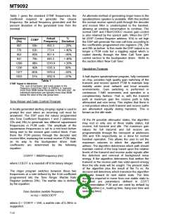
COEFF = 0.128 x Frequency (in Hz)
where COEFF is a rounded off 8 bit binary integer
A single frequency tone may be generated instead of
a dual tone by programming the coefficient at
address 23h to a value of zero. In this case the
frequency of the single output tone is governed by
the coefficient stored at address 24h.
7-9

 MITEL [ MITEL NETWORKS CORPORATION ]