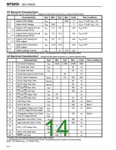
ISO-CMOS MT8950
Codec converts analog signals into the ST-BUS
format while the Data Codec does a similar
conversion for low speed data. The information in
the ST-BUS format can be switched via the Digital
A simplified interface for transmitting and receiving
RS-232 data signals is illustrated in Figure 9. The
Codec is selected to receive and transmit low speed
data in the NRZ format. The data transmitted by the
terminal equipment in the RS-232 format is inverted
and level shifted to TTL-compatible levels before
Switch to any of the
other interfaces and
subsequently transmitted over the appropriate lines
to the remote destination. At the remote end, the
original signal is regenerated by another codec.
The remote equipment can be part of a local area
network or it may be accessed through leased T1/
CEPT digital lines. Access to remote equipment via
the T1/CEPT leased lines is acquired through the T1/
CEPT interface (MT8976). Full duplex transmission
at 1.544 or 2.048 Mbps is possible with this interface.
being fed into the D 1 input on the Codec. The
X
signal is converted into the ST-BUS format and
transmitted via the DSTo output in one channel
timeslot when the ST-BUS interface is enabled by
F1i and CA, as dictated by the system channel
assignment scheme. During this same time period
the Codec accepts the 8 bit data arriving on the
incoming ST-BUS stream which is output at the STo1
pin on the MT8980. The data is decoded and the
original signal input at the remote end is regenerated
The Digital Network Interface Circuit (DNIC), the
MT8972, is capable of providing 160 kbps full duplex
transmission over single telephone pair wiring. This
device can support two 64 kbps channels, allowing
two data codecs to be interfaced to it at the remote
end. Simple, low cost data sets can be constructed
using the data codec and the DNIC.
and output at the D 1 pin. This signal is level
R
shifted, inverted and transmitted to the terminal. The
codec in this particular application requires no other
programming. Loading of the Control Register via
the CSTi input is optional. If this input is tied to
ground, the Codec will operate in mode 0 (the normal
mode). Note that the SCLK input is tied low. Thus
synchronization pulses will not be transmitted and
Digital Switch
MT8980
+ 5V
MT8950
1
2
24
23
22
21
20
19
18
17
16
15
14
13
CSTi
DSTi
C2i
VDD
NC
STi3
STi1
STo0
STo1
3
PRST
NC
4
C4i
F0i
DSTo
F1i
5
NC
6
CA
DR1
DR2
DA
7
DF
8
RxE
DX1
DX2
NRZo
VSS
Timing
Circuitry
9
R
C
SPo
SPi
MPU
10
11
12
DP
SCLK
Channel
Assignment
Circuit
Scan Point
Interface
Line Drivers
/Receivers
TxD
RxD
FROM
DTE
R = 210 KΩ
C = 1.0 µF
RS-232
TTL
Figure 9 - Simplified RS-232 Interface using the Data Codec
6-13

 MITEL [ MITEL NETWORKS CORPORATION ]