MT8950 ISO-CMOS
The Secondary Clock input (SCLK) is normally a
600Hz clock signal. This clock is internally aligned
with the 2.048 MHz input. It is used to generate the
synchronizing pulses and the violation word timing
(when the chip is operating in the local carrier mode).
Note that the 600Hz frequency is an exact multiple of
the most commonly used baud rates, i.e., 300, 2400,
represented by a time interval of one SCLK period
between the pulses. A logic “1” is represented by
two clock periods. In the NRZ mode, the time
interval between consecutive transitions of the signal
carries the information. The modulation scheme is
illustrated in Figure 6. The 8 bit word consists of a
4800, 9600, and 19200.
In synchronous data
Control Register
Bits
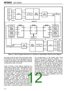
transmission schemes, the receiver timing circuitry
can be kept in sync using the synchronizing pulses
or the violation word when no data is being
transmitted. Other clock frequencies can be used for
specific applications. If this facility is not to be
utilized, the SCLK input can be tied to ground.
Mode of Operation
b7
b6
b5
0
0
0
0
1
1
0
0
1
1
0
0
0
1
0
1
0
1
Normal
Local Carrier
Local Synchronization
Digital Loopback
Data Loopback
Control Interface
An 8 bit word is read into the Control Register via the
CSTi input at the same time as the TEM word is
being shifted in. The chip functions controlled by the
eight bits are summarized in Table 3 and described
in subsequent sections.
Data Loopback - Local
Violation Word
1
1
1
1
0
Normal Mode - Drive Point
Set HIGH.
1
Idle
Bit
Function
Table 4. Modes of Operation
sync bit followed by seven other bits. Bits 1, 4 and 5
in this word reflect the values of bits 2, 3 and 4 in the
Control Register. The remaining four bits in the word
are fixed as zeros. The sync bit is identified by a
time interval equal to four clock periods of SCLK.
The NRZ/RZ input circuitry and the encoder stage
operates normally in this mode.
7,6,5 Device mode control bits. These bits
select one of eight modes of operation
4,3,2 Violation word control bits
1
0
Resets the Data Activity Scan point
Resets the Uncommitted Scan point
Table 3. Summary of Control Register Function
Mode 2: Local Synchronization. In the local sync
mode, the NRZ/RZ output circuitry transmits only
Modes of Operation
sync pulses on D 2. These sync pulses appear as
R
MARK violations in the RZ mode with the time
interval between consecutive pulses equal to four
As mentioned earlier, the data codec can operate in
eight different modes. The specific mode is selected
through bits 7, 6 and 5 in the Control Register. Table
4 summarizes the different modes.
SCLK periods. In the NRZ format D 2 outputs a
R
squarewave with a period equal to eight cycles of
SCLK. D 1 output is held at steady MARK. The
R
NRZ/RZ input circuitry and the encoder stage of the
chip function normally.
Mode 0: Normal. This is the normal transparent
conversion mode of the data codec. The NRZ/RZ
input signal is directly encoded into the TEM format
and output as an ST-BUS channel. The TEM word
for the input ST-BUS channel is decoded and the
regenerated data is output via the NRZ/RZ output
circuitry. Synchronizing pulses are also transmitted
as explained in the preceding paragraphs.
Mode 3: Digital Loopback. In this mode an 8 bit
word from the incoming ST-BUS (DSTi) is sampled
and one ST-BUS frame later, the same word is
looped back to the corresponding outgoing channel
of the ST-BUS (DSTo). This allows the user to test
the ST-BUS transmission path to and from the data
codec.
Mode 1: Local Carrier. In this mode the NRZ/RZ
Mode 4: Data Loopback. This mode permits the
user to test the decoding and encoding operation of
the codec. A known TEM word is sent to the data
codec from the ST-BUS end. This word is decoded
and redirected via the output circuitry to the NRZ/RZ
input circuit and subsequently to the encoder stage
output circuitry transmits an 8 bit word at D 2 (Pin
R
18) by modulating the secondary clock (SCLK). If
the chip has been selected to operate in the RZ
format, this word is transmitted as MARK
Violations. The time interval between consecutive
pulses specifies the binary value. A logical zero is
6-10

 MITEL [ MITEL NETWORKS CORPORATION ]