ISO-CMOS MT8950
MARK
MARK
NRZ
Equivalent
SPACE
SPACE
D
D
Bipolar RZ
Equivalent
D
D
V
V
RxE
Establishes MARK polarity. See text for complete explanation.
52 µs. Nom. or
104 µs. Nom. or
> 125 µs
DX1 Input
4 µs. Min.
Tb Max.
MARK Pulses
(Polarity
Established)
Tb = Bit Period
D
D
125 µs.
Min.
DX2 Input
SPACE Pulses.
D
D
V
V
Signal Regenerated at Remote End
125 µs. Min.
D
D
35 µs. Nom.
DR2 Output
MARK Pulses
52 µs. Nom. or
104 µs. Nom. or
> 125 µs
125 µs.
Min.
DR1 Output
SPACE Pulses
35 µs. Nom.
D
D
V
V
V = Violations Pulse; D = Data Pulse
Figure 4 - Example Input/Output Waveform in the RZ format (DF=HIGH)
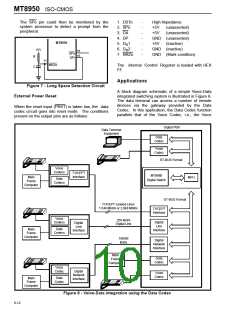
word on the first rising edge of the clock after F1i
and CA are taken low. The 8 bit TEM word from
the input ST-BUS stream is clocked into the device
on the negative edge of the C2i clock. For proper
codec operation, the ST-BUS interface (DSTo, DSTi,
and CSTi) should be enabled for only 8 clock periods
of the C2i clock in any 125µs period (one ST-BUS
frame time) as shown in Figure 11. All data input
and output at the ST-BUS interface takes place at
2.048 Mbps.
52 µs. Nom. or
104 µs. Nom. or
> 125 µs
DX1
NRZ Input
MARK
MARK
SPACE
SPACE
125 µs.
Min.
4 µs. Min.
121 µs. Max.
DX2
Secondary
Input
125 µs. Min.
Signal Regenerated at Remote End
MARK
MARK
DR1
Data
Output
SPACE
SPACE
DR2
Secondary
Output
Each transition on this output denotes a pulse input at DX2 on the remote end
Figure 5 - Example Input/Output Waveform in the NRZ format (DF=LOW)
6-9

 MITEL [ MITEL NETWORKS CORPORATION ]