ISO-CMOS MT8950
for transmission out on the ST-BUS output pin
(DSTo). The NRZ/RZ inputs (Pins 9 and 10) are
functionally disconnected from the input circuitry.
The outputs (pins 18 and 19) are in a non-active
1. Data Activity (DA): This output goes from high
to low when a SPACE signal, indicating the
beginning of data activity, is received by the NRZ/
RZ input circuitry. The level on this pin is reset by
setting bit 1 of the Control Register to logic “1”.
state, i.e., D 1 is steady LOW and D 2 is steady
R
R
HIGH.
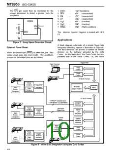
2. Scan Point output (SPo): This output is set
LOW whenever SPi input undergoes a low to high
transition. It is reset by a logic “1” in bit 0 of the
Control Register. The SPi input is generally used
in conjunction with pin 11 to detect a long SPACE
condition in the data. The external circuitry
required to utilize this feature is illustrated in
Figure 7. Note that Pin 11 (NRZo) is an open
drain output. The NRZ/RZ data input to the
codec is converted to the NRZ format and output
on this pin. The RC time constant for the circuit
shown in Figure 7 can be set to detect SPACE
conditions of varying time durations. The length
of the long SPACE detected is given by
Mode 5: Data Loopback - Local Violation Word.
This mode can be used for testing the operation of
the chip in the local carrier mode. The Violation word
is generated as in the local carrier mode. However,
the modulated signal is not output on D 2. It is
R
rerouted to the NRZ/RZ input circuit, encoded into
the TEM format and output on DSTo.
Mode 6: Normal Mode - Drive Point Activated.
The drive point output (Pin 14) is set HIGH in this
mode. The codec operation is normal in every other
respect. This drive point can be used to control
external circuitry. It is reset when the mode of
operation is changed.
TSP=0.7RC
Where TSP is the duration of the SPACE in
Mode 7: Idle. In the idle mode D 1 and D 2 outputs
milliseconds.
A long SPACE of 150ms is
R
R
are in a non-active state, i.e., D 1 is steady LOW
generated when the BREAK key on a data
terminal is depressed. To detect this signal, a
value of R equal to 210 kΩ and C equal to 1.0µF
can be used.
R
and D 2 is steady HIGH. The encoder stage and the
R
input circuitry operates normally.
Device Monitoring Features
There are two output pins which can be used to
monitor the codec.
CRB = Control Register Bit
SYNCH
b0
b1
b2 b3
b4
b5
b6
SYNCH
b0
b1
b2 b3
b4
b5
b6
CRB2
CRB3 CRB4
CRB2
CRB3 CRB4
35 µs Nominal
DR2
Output
(RZ
Mode)
b0
1.67
b1
b2
1.67
msec
b3
1.67
b4
b5
b6
1.67
msec
SYNCH
SYNCH
6.7 ± 0.83 msec
0=1.67 msec
0=1.67 msec 0=1.67 msec
msec 1=3.33 msec
msec 1=3.33 msec 1=3.33 msec
CRB2
CRB3 CRB4
DR2
Output
(NRZ
Mode)
Note: The polarity of this output can be inverted - depending on the state of the last transition.
Figure 6 - Violation Word Timing in the Local Carrier Mode for a 600Hz input to SCLK
6-11

 MITEL [ MITEL NETWORKS CORPORATION ]