MT8950 ISO-CMOS
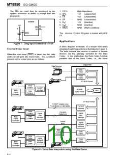
The SPo pin could then be monitored by the
system processor to detect a prompt from the
peripheral.
1. DSTo
2. SPo
3. DA
-
-
-
-
-
-
-
High Impedance
+5V
+5V
(unasserted)
(unasserted)
4. DP
GND (unasserted)
+5V (inactive)
MT8950
5. D 1
R
6. D 2
GND (inactive)
+5V
R
16
SPo
7. NRZo
GND (Mark condition)
15
R
C
SPi
11
NRZo
The internal Control Register is loaded with HEX
FF.
Applications
Figure 7 - Long Space Detection Circuit
External Power Reset
A block diagram schematic of a simple Voice-Data
integrated switching system is illustrated in Figure 8.
The data terminal can access a number of remote
devices via the gateway provided by the Data
Codec. In this application, the Data Codec function
parallels that of the Voice Codec, i.e., the Voice
When the reset input (PRST) is taken low, the data
codec circuit goes into reset mode. The conditions
present on the output pins are as follows:
Digital PBX
Data Terminal
Equipment
Data
Codec
Voice
Codec
ST-BUS Format
Voice
Codecs
T1/CEPT
Interface
MT8980
Main
Frame
MPU
Data
Codecs
Digital Switch
Computer
ST-BUS Format
T1/CEPT Leased Lines
1.544 Mbit/s or 2.048 Mbit/s
T1/CEPT
Interface
Voice
Codecs
256 kbit/s
Digital Line
Digital
Line
Interface
Digital
Line
Interface
Data
Codecs
Main
Frame
Computer
160/80
kbit/s
Digital
Network
Interface
Main
Frame
Computer
Data
Codec
Voice
Codec
Digital
Network
Interface
Voice
Codec
Data
Codec
Main
Frame
Computer
Figure 8 - Voice-Data integration using the Data Codec
6-12

 MITEL [ MITEL NETWORKS CORPORATION ]