MT8950 ISO-CMOS
RTS
CTS
DSR
Random Logic
or
Microcomputer
NRZ /
Bipolar
Converter
Line
Driver /
Receiver
Level
Converters
DTR
Bipolar RZ signal
RLSD
TxD
RxD
DTE
RS-232
TTL
Digital PBX
MT8950
DX2 DSTi
MT8980
MT8950
Receiver
Receiver
DSTi
STo1
STo3
STi3
DX2
DX1
Bipolar to
Unipolar
Converter
Bipolar to
Unipolar
Converter
DX1
DSTo
DSTo
STi1
DR2
DR1
Unipolar
to Bipolar
Converter
Unipolar
to Bipolar
Converter
DR2
DR1
Line Driver
Line Driver
MPU
TTL
RS-232
DTE
RTS
CTS
DSR
DTR
RLSD
TxD
Random Logic
NRZ /
Line
Level
Converters
or
Bipolar
Driver /
Bipolar RZ signal
Microcomputer
Converter
Receiver
RxD
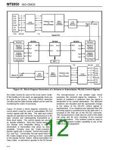
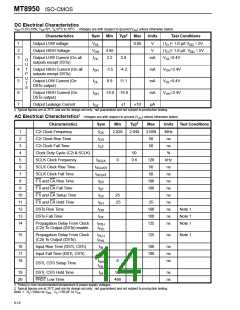
Figure 10 - Block Diagram Illustration of a Scheme to Submultiplex RS-232 Control Signals
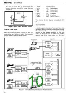
the codec cannot be used in the local carrier mode.
If this facility is to be used, an appropriate clock can
be input to the device. The long SPACE detection
circuitry and the Data Activity output can be used for
monitoring the codec if necessary.
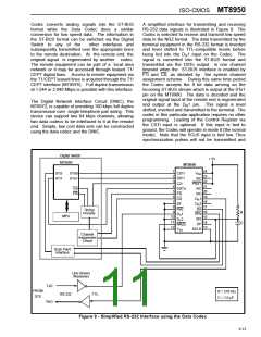
The microprocessor or the random logic circuit
examines the received signal for violations. If a
stream of violations is detected, then the signal is
interpreted to be control information. The detected
violations are decoded and the appropriate change
in the status of the RS-232 control signals is
implemented. If no violations are detected then the
incoming signal is considered to be the data and it is
rerouted to the RxD pin of the RS-232 connector.
The microprocessor could also be used in the initial
call setup and for error checking of the received
control information. This scheme could be used to
provide transparent modem capability to any of the
ST-BUS based equipment.
Figure 10 shows a block diagram schematic of a
circuit which could be used to submultiplex RS-232
control signals with the data. The data and control
signals are operated on by the microprocessor or the
logic circuitry and subsequently transmitted as a
three level signal. The control signals are encoded
as bipolar violations. Since the control status does
not change very frequently during a call, this
information is transmitted only when no data is
available. Circuitry near the Codec converts the
bipolar signal into a unipolar format and inputs it at
D 1 and D 2. Conversely, the low speed data from
X
X
the Codec output at D 1 and D 2 is first converted
R
R
to the bipolar format before being transmitted.The
Data Codec is selected to operate in the RZ format.
6-14

 MITEL [ MITEL NETWORKS CORPORATION ]