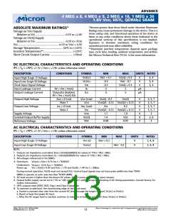
ADVANCE
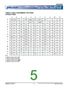
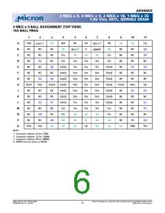
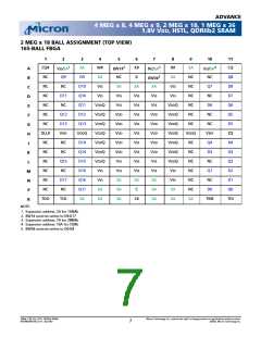
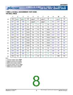
4 MEG x 8, 4 MEG x 9, 2 MEG x 18, 1 MEG x 36
1.8V VDD, HSTL, QDRIIb2 SRAM
FBGA BALL DESCRIPTIONS
SYMBOL
TYPE
DESCRIPTION
SA
Input
Synchronous Address Inputs: These inputs are registered and must meet the setup and hold
times around the rising edge of K for READ cycles and K# for WRITE cycles. See Ball
Assignment figures for address expansion inputs. All transactions operate on a burst of two
words (one clock period of bus activity). These inputs are ignored when both ports are
deselected.
R#
Input
Input
Input
Synchronous Read: When LOW, this input causes the address inputs to be registered and a
READ cycle to be initiated. This input must meet setup and hold times around the rising edge
of K.
W#
Synchronous Write: When LOW, this input causes the address inputs to be registered and a
WRITE cycle to be initiated. This input must meet setup and hold times around the rising
edge of K.
BW_#
NW_#
Synchronous Byte Writes (or Nibble Writes on the x8): When LOW, these inputs cause their
respective Bytes to be registered and written if W# had initiated a WRITE cycle. These signals
must meet setup and hold times around the rising edges of K and K# for each of the two
rising edges comprising the WRITE cycle. See Ball Assignment figures for signal to data
relationships.
K
K#
Input
Input
Input Clock: This input clock pair registers address and control inputs on the rising edge of K,
and registers data on the rising edge of K and the rising edge of K#. K# is ideally 180 degrees
out of phase with K. All synchronous inputs must meet setup and hold times around the clock
rising edges.
C
C#
Output Clock: This clock pair provides a user-controlled means of tuning device output data.
The rising edge of C is used as the output timing reference for second output data. The rising
edge of C# is used as the output reference for first output data. Ideally, C# is 180 degrees out
of phase with C. C and C# may be tied HIGH to force the use of K and K# as the output
reference clocks instead of having to provide C and C# clocks. If tied HIGH, these inputs may
not be allowed to toggle during device operation.
TMS
TDI
Input
Input
Input
Input
IEEE 1149.1 Test Inputs: 1.8V I/O levels. These balls may be left as No Connects if the JTAG
function is not used in the circuit.
TCK
VREF
ZQ
IEEE 1149.1 Clock Input: 1.8V I/O levels. This ball must be tied to VSS if the JTAG function is not
used in the circuit.
HSTL Input Reference Voltage: Nominally VDDQ/2, but may be adjusted to improve system
noise margin. Provides a reference voltage for the HSTL input buffer trip point.
Output Impedance Matching Input: This input is used to tune the device outputs to the
system data bus impedance. DQ output impedance is set to 0.2 x RQ, where RQ is a resistor
from this ball to ground. Alternately, this ball can be connected directly to VDDQ to enable
the minimum impedance mode. This ball cannot be connected directly to GND or left
unconnected.
DLL#
D_
Input
Input
DLL Disable: When LOW, this input causes the DLL to be bypassed for stable, low-frequency
operation.
Synchronous Data Inputs: Input data must meet setup and hold times around the rising edges
of K and K# during WRITE operations. See Ball Assignment figures for ball site location of
individual signals. The x8 device uses D0-D7. Remaining signals are NC. The x9 device uses D0-
D8. Remaining signals are NC. The x18 device uses D0–D17. Remaining signals are NC. The x36
device uses D0–D35. Remaining signals are NC.
CQ#, CQ
TDO
Output
Output
Synchronous Echo Clock Outputs: The edges of these outputs are tightly matched to the
synchronous data outputs and can be used as data valid indication. These signals run freely
and do not stop when Q tri-states.
IEEE 1149.1 Test Output: 1.8V I/0 level.
36Mb: 1.8V VDD, HSTL, QDRIIb2 SRAM
MT54W2MH18B_A.fm - Rev 9/02
Micron Technology, Inc., reserves the right to change products or specifications without notice.
9
©2002, Micron Technology Inc.

 MICRON [ MICRON TECHNOLOGY ]