2 MEG x 16
ASYNC/PAGE/BURST FLASH MEMORY
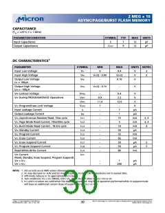
CAPACITANCE
(TA = +25ºC; f = 1 MHz)
PARAMETER/CONDITION
Input Capacitance
SYMBOL
TYP
7
MAX
12
UNITS
pF
C
Output Capacitance
COUT
9
12
pF
1
DC CHARACTERISTICS
PARAMETER
SYMBOL
VIL
MIN
MAX
UNITS NOTES
Input Low Voltage
Input High Voltage
0
0.4
V
V
V
2
2
VIH
VCCQ - 0.4V
–
VCCQ
0.10
Output Low Voltage
IOL = 100µA
VOL
Output High Voltage
IOH = -100µA
VOH
VCCQ - 0.1V
–
V
VPP Lockout Voltage
VPPLK
VPP1
VPP2
VLKO
IL
–
0.9
11.4
1
0.4
2.2
12.6
–
V
VPP During PROGRAM/ERASE Operations
V
V
VCC Program/Erase Lock Voltage
Input Leakage Current
V
–
1
µA
µA
mA
mA
mA
µA
mA
mA
µA
µA
mA
Output Leakage Current
IOZ
–
1
VCC Asynchronous Random Read, 70ns cycle
VCC Page Mode Read Current, 70ns/30ns cycle
VCC Burst Mode Read Current , 18.5ns cycle
VCC Standby Current
ICC1
ICC2
ICC3
ICC4
ICC5
ICC6
ICC7
ICC8
ICC9
IPP1
–
15
5
3, 4
3, 4
4
–
–
10
50
55
65
50
50
80
–
VCC Program Current
–
VCC Erase Current
–
VCC Erase Suspend Current
–
5
5
VCC Program Suspend Current
Read-While-Write Current
–
–
VPP Current
(Read, Standby, Erase Suspend, Program Suspend)
VPP ≤ VCC
VPP ≥ VCC
–
–
1
200
µA
µA
NOTE: 1. All currents are in RMS unless otherwise noted.
2. VIL may decrease to -0.4V and VIH may increase to VCCQ + 0.3V for durations not to exceed 20ns.
3. APS mode reduces ICC to approximately ICC4 levels.
4. Test conditions: Vcc = VCC (MAX), CE# = VIL, OE# = VIH. All other inputs = VIH or VIL.
5. ICC7 and ICC8 values are valid when the device is deselected. Any READ operation performed while in suspend mode
will have an additional current draw of suspend current (ICC7 or ICC8).
2 Meg x 16 Async/Page/Burst Flash Memory
MT28F322D20FH_4.p65 – Rev. 4, Pub. 7/02
Micron Technology, Inc., reserves the right to change products or specifications without notice.
©2002, Micron Technology, Inc.
30

 MICRON [ MICRON TECHNOLOGY ]