PIC24FJ64GA104 FAMILY
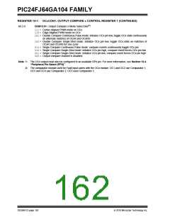
REGISTER 14-1: OCxCON1: OUTPUT COMPARE x CONTROL REGISTER 1 (CONTINUED)
bit 2-0
OCM<2:0>: Output Compare x Mode Select bits(1)
111= Center-Aligned PWM mode on OCx
110= Edge-Aligned PWM mode on OCx
101= Double Compare Continuous Pulse mode: initialize OCx pin low, toggle OCx state continuously
on alternate matches of OCxR and OCxRS
100= Double Compare Single-Shot mode: initialize OCx pin low, toggle OCx state on matches of
OCxR and OCxRS for one cycle
011= Single Compare Continuous Pulse mode: compare events continuously toggle OCx pin
010= Single Compare Single-Shot mode: initialize OCx pin high, compare event forces OCx pin low
001= Single Compare Single-Shot mode: initialize OCx pin low, compare event forces OCx pin high
000= Output compare channel is disabled
Note 1: The OCx output must also be configured to an available RPn pin. For more information, see Section 10.4
“Peripheral Pin Select (PPS)”.
2: The comparator module used for Fault input varies with the OCx module. OC1 and OC2 use Comparator 1;
OC3 and OC4 use Comparator 2; OC5 uses Comparator 3.
DS39951C-page 162
2010 Microchip Technology Inc.

 MICROCHIP [ MICROCHIP ]