PIC24FJ64GA104 FAMILY
14.3.1
PWM PERIOD
14.3.2
PWM DUTY CYCLE
In edge aligned PWM mode, the period is specified by
the value of OCxRS register. In center aligned PWM
mode, the period of the synchronization source such as
Timer's PRy specifies the period. The period in both
cases can be calculated using Equation 14-1.
The PWM duty cycle is specified by writing to the
OCxRS and OCxR registers. The OCxRS and OCxR
registers can be written to at any time, but the duty
cycle value is not latched until a period is complete.
This provides a double buffer for the PWM duty cycle
and is essential for glitchless PWM operation.
EQUATION 14-1: CALCULATING THE PWM
PERIOD(1)
Some important boundary parameters of the PWM duty
cycle include:
PWM Period = [Value + 1] x TCY x (Prescaler Value)
• Edge-Aligned PWM
- If OCxR and OCxRS are loaded with 0000h,
the OCx pin will remain low (0% duty cycle).
Where: Value = OCxRS in Edge-Aligned PWM mode
and can be PRy in Center-Aligned PWM mode
(If TMRy is the sync source).
- If OCxRS is greater than OCxR, the pin will
remain high (100% duty cycle).
Note 1: Based on TCY = TOSC * 2; Doze mode
• Center-Aligned PWM (with TMRy as the sync
source)
and PLL are disabled.
- If OCxR, OCxRS and PRy are all loaded with
0000h, the OCx pin will remain low (0% duty
cycle).
- If OCxRS is greater than PRy, the pin will go
high (100% duty cycle).
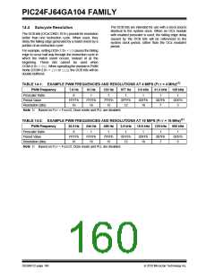
See Example 14-1 for PWM mode timing details.
Table 14-1 and Table 14-2 show example PWM
frequencies and resolutions for a device operating at
4 MIPS and 10 MIPS, respectively.
EQUATION 14-2: CALCULATION FOR MAXIMUM PWM RESOLUTION(1)
FCY
log10
(
)
FPWM • (Prescale Value)
Maximum PWM Resolution (bits) =
log10(2)
bits
Note 1: Based on FCY = FOSC/2; Doze mode and PLL are disabled.
EXAMPLE 14-1:
PWM PERIOD AND DUTY CYCLE CALCULATIONS(1)
1. Find the OCxRS register value for a desired PWM frequency of 52.08 kHz, where FOSC = 8 MHz with PLL (32 MHz device
clock rate) and a prescaler setting of 1:1 using Edge-Aligned PWM mode.
TCY = 2 * TOSC = 62.5 ns
PWM Period = 1/PWM Frequency = 1/52.08 kHz = 19.2 s
PWM Period = (OCxRS + 1) • TCY • (OCx Prescale Value)
19.2 s
OCxRS
= (OCxRS + 1) • 62.5 ns • 1
= 306
2. Find the maximum resolution of the duty cycle that can be used with a 52.08 kHz frequency and a 32 MHz device clock rate:
PWM Resolution = log10(FCY/FPWM)/log102) bits
= (log10(16 MHz/52.08 kHz)/log102) bits
= 8.3 bits
Note 1: Based on TCY = 2 * TOSC; Doze mode and PLL are disabled.
2010 Microchip Technology Inc.
DS39951C-page 159

 MICROCHIP [ MICROCHIP ]