PIC17C75X
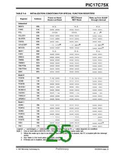
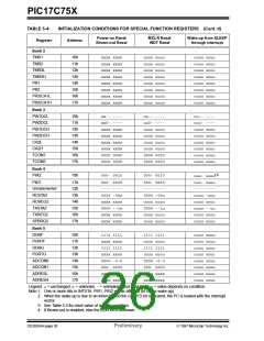
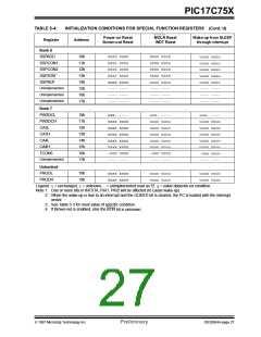
TABLE 5-4:
Register
INITIALIZATION CONDITIONS FOR SPECIAL FUNCTION REGISTERS
Power-on Reset
Brown-out Reset
MCLR Reset
WDT Reset
Wake-up from SLEEP
through interrupt
Address
Unbanked
INDF0
FSR0
00h
01h
02h
N.A.
xxxx xxxx
0000h
N.A.
uuuu uuuu
0000h
N.A.
uuuu uuuu
PC + 1(2)
uuuu uuuu
1111 uuuu
0000 000-
PCL
PCLATH
ALUSTA
T0STA
03h
04h
05h
06h
0000 0000
1111 xxxx
0000 000-
0000 0000
1111 uuuu
0000 000-
CPUSTA(3)
INTSTA
--11 1100(4)
0000 0000
--11 qquu(4)
0000 0000
--uu qquu(4)
uuuu uuuu(1)
N.A.
07h
INDF1
08h
09h
0Ah
0Bh
0Ch
0Dh
0Eh
0Fh
N.A.
N.A.
uuuu uuuu
uuuu uuuu
uuuu uuuu
uuuu uuuu
0000 0000
0000 0000
0000 0000
FSR1
xxxx xxxx
xxxx xxxx
xxxx xxxx
xxxx xxxx
0000 0000
0000 0000
0000 0000
uuuu uuuu
uuuu uuuu
uuuu uuuu
uuuu uuuu
uuuu uuuu
uuuu uuuu
uuuu uuuu
WREG
TMR0L
TMR0H
TBLPTRL
TBLPTRH
BSR
Bank 0
PORTA
DDRB
10h
11h
12h
13h
14h
15h
16h
17h
0-xx xxxx
1111 1111
xxxx xxxx
0000 -00x
xxxx xxxx
0000 --1x
xxxx xxxx
xxxx xxxx
0-uu uuuu
1111 1111
uuuu uuuu
0000 -00u
uuuu uuuu
0000 --1u
uuuu uuuu
uuuu uuuu
u-uu uuuu
uuuu uuuu
uuuu uuuu
uuuu -uuu
uuuu uuuu
uuuu --uu
uuuu uuuu
uuuu uuuu
PORTB
RCSTA1
RCREG1
TXSTA1
TXREG1
SPBRG1
Bank 1
DDRC
PORTC
DDRD
PORTD
DDRE
PORTE
PIR1
10h
11h
12h
13h
14h
15h
16h
1111 1111
xxxx xxxx
1111 1111
xxxx xxxx
---- 1111
---- xxxx
x000 0010
1111 1111
uuuu uuuu
1111 1111
uuuu uuuu
---- 1111
---- uuuu
u000 0010
uuuu uuuu
uuuu uuuu
uuuu uuuu
uuuu uuuu
---- uuuu
---- uuuu
uuuu uuuu(1)
uuuu uuuu
PIE1
17h
0000 0000
0000 0000
Legend: u= unchanged, x= unknown, -= unimplemented read as '0', q= value depends on condition.
Note 1: One or more bits in INTSTA, PIR1, PIR2 will be affected (to cause wake-up).
2: When the wake-up is due to an interrupt and the GLINTD bit is cleared, the PC is loaded with the interrupt
vector.
3: See Table 5-3 for reset value of specific condition.
4: If Brown-out is enabled, else the BOR bit is unknown.
1997 Microchip Technology Inc.
Preliminary
DS30264A-page 25

 MICROCHIP [ MICROCHIP ]