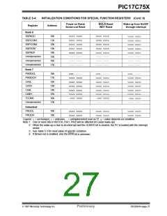
PIC17C75X
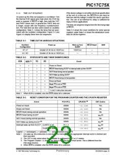
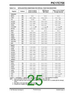
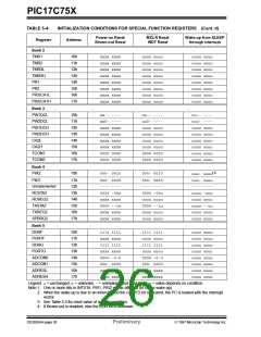
TABLE 5-4:
Register
INITIALIZATION CONDITIONS FOR SPECIAL FUNCTION REGISTERS (Cont.’d)
Power-on Reset
Brown-out Reset
MCLR Reset
WDT Reset
Wake-up from SLEEP
through interrupt
Address
Bank 6
SSPADD
10h
11h
12h
13h
14h
15h
16h
17h
0000 0000
0000 0000
0000 0000
0000 0000
xxxx xxxx
---- ----
---- ----
---- ----
0000 0000
0000 0000
0000 0000
0000 0000
uuuu uuuu
---- ----
---- ----
---- ----
uuuu uuuu
uuuu uuuu
uuuu uuuu
uuuu uuuu
uuuu uuuu
---- ----
---- ----
---- ----
SSPCON1
SSPCON2
SSPSTAT
SSPBUF
Unimplemented
Unimplemented
Unimplemented
Bank 7
PW3DCL
PW3DCH
CA3L
10h
11h
12h
13h
14h
15h
16h
17h
xxx- ----
xxxx xxxx
xxxx xxxx
xxxx xxxx
xxxx xxxx
xxxx xxxx
-000 0000
---- ----
uuu- ----
uuuu uuuu
uuuu uuuu
uuuu uuuu
uuuu uuuu
uuuu uuuu
-000 0000
---- ----
uuu- ----
uuuu uuuu
uuuu uuuu
uuuu uuuu
uuuu uuuu
uuuu uuuu
-uuu uuuu
---- ----
CA3H
CA4L
CA4H
TCON3
Unimplemented
Unbanked
PRODL
18h
19h
xxxx xxxx
xxxx xxxx
uuuu uuuu
uuuu uuuu
uuuu uuuu
uuuu uuuu
PRODH
Legend: u= unchanged, x= unknown, -= unimplemented read as '0', q= value depends on condition.
Note 1: One or more bits in INTSTA, PIR1, PIR2 will be affected (to cause wake-up).
2: When the wake-up is due to an interrupt and the GLINTD bit is cleared, the PC is loaded with the interrupt
vector.
3: See Table 5-3 for reset value of specific condition.
4: If Brown-out is enabled, else the BOR bit is unknown.
1997 Microchip Technology Inc.
Preliminary
DS30264A-page 27

 MICROCHIP [ MICROCHIP ]