PIC17C75X
5.1.2
POWER-UP TIMER (PWRT)
5.1
Power-on Reset (POR), Power-up
Timer (PWRT), Oscillator Start-up
Timer (OST), and Brown-out Reset
(BOR)
The Power-up Timer provides a fixed 96 ms time-out
(nominal) on power-up. This occurs from the rising
edge of the POR signal and after the first rising edge of
MCLR (detected high). The Power-up Timer operates
on an internal RC oscillator. The chip is kept in RESET
as long as the PWRT is active. In most cases the
PWRT delay allows VDD to rise to an acceptable level.
5.1.1
POWER-ON RESET (POR)
The Power-on Reset circuit holds the device in reset
until VDD is above the trip point (in the range of 1.4V -
2.3V). The devices produce an internal reset for both
rising and falling VDD. To take advantage of the POR,
just tie the MCLR/VPP pin directly (or through a resistor)
to VDD. This will eliminate external RC components
usually needed to create Power-on Reset. A minimum
rise time for VDD is required. See Electrical Specifica-
tions for details.
The power-up time delay will vary from chip to chip and
with VDD and temperature. See DC parameters for
details.
5.1.3
OSCILLATOR START-UP TIMER (OST)
The Oscillator Start-up Timer (OST) provides a 1024
oscillator cycle (1024TOSC) delay after MCLR is
detected high or a wake-up from SLEEP event occurs.
Figure 5-2 and Figure 5-3 show two possible POR cir-
cuits.
The OST time-out is invoked only for XT and LF oscil-
lator modes on a Power-on Reset or a Wake-up from
SLEEP.
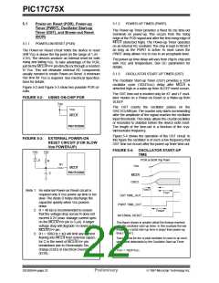
FIGURE 5-2: USING ON-CHIP POR
VDD
The OST counts the oscillator pulses on the
OSC1/CLKIN pin.The counter only starts incrementing
after the amplitude of the signal reaches the oscillator
input thresholds.This delay allows the crystal oscillator
or resonator to stabilize before the device exits reset.
The length of the time-out is a function of the crys-
tal/resonator frequency.
VDD
MCLR
PIC17CXXX
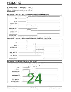
Figure 5-4 shows the operation of the OST circuit. In
this figure the oscillator is of such a low frequency that
OST time out occurs after the power-up timer time-out.
FIGURE 5-3: EXTERNAL POWER-ON
RESET CIRCUIT (FOR SLOW
VDD POWER-UP)
FIGURE 5-4: OSCILLATOR START-UP
TIME
VDD
VDD
POR or BOR Trip Point
D
R
R1
VDD
MCLR
PIC17CXXX
C
MCLR
OSC2
TOSC1
TOST
Note 1: An external Power-on Reset circuit is
required only if VDD power-up time is too
slow. The diode D helps discharge the
capacitor quickly when VDD powers
down.
OST TIME_OUT
PWRT TIME_OUT
2: R < 40 kΩ is recommended to ensure
that the voltage drop across R does not
exceed 0.2V (max. leakage current spec.
on the MCLR/VPP pin is 5 µA). A larger
voltage drop will degrade VIH level on the
MCLR/VPP pin.
3: R1 = 100Ω to 1 kΩ will limit any current
flowing into MCLR from external capaci-
tor C in the event of MCLR/VPP pin
breakdown due to Electrostatic Dis-
charge (ESD) or Electrical Overstress
(EOS).
TPWRT
INTERNAL RESET
This figure shows in greater detail the timings involved
with the oscillator start-up timer. In this example the low
frequency crystal start-up time is larger than power-up
time (TPWRT).
Tosc1 = time for the crystal oscillator to react to an oscil-
lation level detectable by the Oscillator Start-up Timer
(ost).
TOST = 1024TOSC.
DS30264A-page 22
Preliminary
1997 Microchip Technology Inc.

 MICROCHIP [ MICROCHIP ]