PIC17C75X
5.1.4
TIME-OUT SEQUENCE
If the device voltage is not within electrical specification
at the end of a time-out, the MCLR/VPP pin must be
held low until the voltage is within the device specifica-
tion. The use of an external RC delay is sufficient for
many of these applications.
On power-up the time-out sequence is as follows: First
the internal POR signal goes high when the POR trip
point is reached. If MCLR is high, then both the OST
and PWRT timers start. In general the PWRT time-out
is longer, except with low frequency crystals/resona-
tors. The total time-out also varies based on oscillator
configuration. Table 5-1 shows the times that are asso-
ciated with the oscillator configuration. Figure 5-5 and
Figure 5-6 display these time-out sequences.
The time-out sequence begins from the first rising edge
of MCLR.
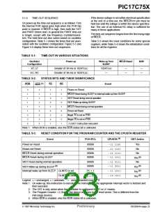
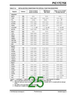
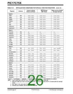
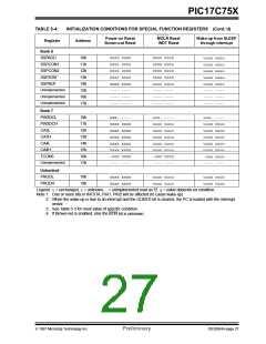
Table 5-3 shows the reset conditions for some special
registers, while Table 5-4 shows the initialization condi-
tions for all the registers.
TABLE 5-1:
TIME-OUT IN VARIOUS SITUATIONS
Oscillator
Configuration
Power-up
Wake up from
SLEEP
MCLR Reset
BOR
XT, LF
Greater of: 96 ms or 1024TOSC
Greater of: 96 ms or 1024TOSC
1024TOSC
—
—
—
—
—
EC, RC
TABLE 5-2:
STATUS BITS AND THEIR SIGNIFICANCE
(1)
POR
TO
PD
Event
BOR
0
1
1
1
1
1
0
0
x
0
1
1
1
1
0
0
0
x
1
1
0
0
1
x
0
x
1
1
0
1
0
1
x
x
0
1
Power-on Reset
MCLR Reset during SLEEP or interrupt wake-up from SLEEP
WDT Reset during normal operation
WDT Wake-up during SLEEP
MCLR Reset during normal operation
Brown-out Reset
Illegal, TO is set on POR
Illegal, PD is set on POR
CLRWDTinstruction executed
Note 1: When BOR is enabled, else the BOR status bit is unknown
TABLE 5-3:
RESET CONDITION FOR THE PROGRAM COUNTER AND THE CPUSTA REGISTER
(4)
Event
PCH:PCL
CPUSTA
OST Active
Power-on Reset
Brown-out Reset
0000h
--11 1100
Yes
0000h
0000h
0000h
--11 1101
--11 1111
--11 1011
No
No
MCLR Reset during normal operation
MCLR Reset during SLEEP
(2)
Yes
WDT Reset during normal operation
0000h
0000h
--11 0111
--11 0011
No
(3)
(2)
WDT Wake-up during SLEEP
Yes
(2)
Interrupt wake-up from SLEEP GLINTD is set
GLINTD is clear
PC + 1
--11 1011
--10 1011
Yes
(1)
(2)
PC + 1
Yes
Legend: u= unchanged, x= unknown, -= unimplemented read as '0'.
Note 1: On wake-up, this instruction is executed. The instruction at the appropriate interrupt vector is fetched and
then executed.
2: The OST is only active when the Oscillator is configured for XT or LF modes.
3: The Program Counter = 0, that is, the device branches to the reset vector. This is different from the
mid-range devices.
4: When BOR is enabled, else the BOR status bit is unknown.
1997 Microchip Technology Inc.
Preliminary
DS30264A-page 23

 MICROCHIP [ MICROCHIP ]