PIC17C75X
(RB0/CAP1, RB1/CAP2, RG4/CAP3, and RE3/CAP4),
one for each capture register pair.The capture pins are
multiplexed with the I/O pins. An event can be:
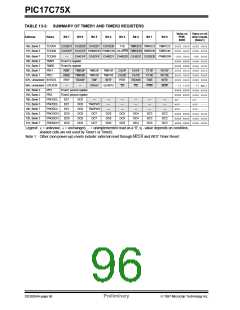
13.2
Timer3
Timer3 is a 16-bit timer consisting of the TMR3H and
TMR3L registers. TMR3H is the high byte of the timer
and TMR3L is the low byte. This timer has an associ-
ated 16-bit period register (PR3H/CA1H:PR3L/CA1L).
This period register can be software configured to be a
another 16-bit capture register.
• A rising edge
• A falling edge
• Every 4th rising edge
• Every 16th rising edge
Each 16-bit capture register has an interrupt flag asso-
ciated with it. The flag is set when a capture is made.
The capture modules are truly part of the Timer3 block.
Figure 13-8 and Figure 13-9 show the block diagrams
for the two modes of operation.
When the TMR3CS bit (TCON1<2>) is clear, the timer
increments every instruction cycle (Fosc/4). When
TMR3CS is set, the counter increments on every falling
edge of the RB5/TCLK3 pin. In either mode, the
TMR3ON bit must be set for the timer/counter to incre-
ment. When TMR3ON is clear, the timer will not incre-
ment or set flag bit TMR3IF.
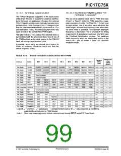
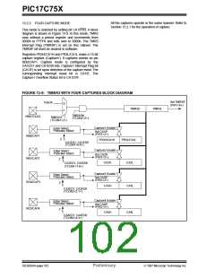
13.2.1 THREE CAPTURE AND ONE PERIOD
REGISTER MODE
Timer3 has two modes of operation, depending on the
CA1/PR3 bit (TCON2<3>). These modes are:
In this mode registers PR3H/CA1H and PR3L/CA1L
constitute a 16-bit period register. A block diagram is
shown in Figure 13-8. The timer increments until it
equals the period register and then resets to 0000h on
the next timer clock. TMR3 Interrupt Flag bit (TMR3IF)
is set at this point. This interrupt can be disabled by
clearing the TMR3 Interrupt Enable bit (TMR3IE).
TMR3IF must be cleared in software.
• Three capture and one period register mode
• Four capture register mode
The PIC17C75X has up to four 16-bit capture registers
that capture the 16-bit value of TMR3 when events are
detected on capture pins. There are four capture pins
FIGURE 13-8: TIMER3 WITH THREE CAPTURE AND ONE PERIOD REGISTER BLOCK DIAGRAM
TMR3CS
(TCON1<2>)
PR3H/CA1H
PR3L/CA1L
TMR3L
Set TMR3IF
(PIR1<6>)
CCoommppaarraatotor<r8x>16
Equal
Reset
0
Fosc/4
TMR3H
1
TMR3ON
(TCON2<2>)
RB5/TCLK3
RB1/CAP2
Capture2
Enable
Edge select,
Prescaler select
CA2H
CA2L
2
Set CA2IF
(PIR1<3>)
CA2ED1: CA2ED0
(TCON1<7:6>)
Capture3
Enable
Edge select,
Prescaler select
RG4/CAP3
CA3H
CA3L
2
Set CA3IF
(PIR2<2>)
CA3ED1: CA3ED0
(TCON3<2:1>)
Capture4
Enable
Edge select,
Prescaler select
RE3/CAP4
CA4H
CA4L
2
Set CA4IF
(PIR2<3>)
CA4ED1: CA4ED0
(TCON3<4:3>)
DS30264A-page 100
Preliminary
1997 Microchip Technology Inc.

 MICROCHIP [ MICROCHIP ]