PIC17C75X
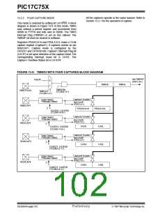
13.2.2 FOUR CAPTURE MODE
All the captures operate in the same manner. Refer to
Section 13.2.1 for the operation of capture.
This mode is selected by setting bit CA1/PR3. A block
diagram is shown in Figure 13-9. In this mode, TMR3
runs without a period register and increments from
0000h to FFFFh and rolls over to 0000h. The TMR3
interrupt Flag (TMR3IF) is set on this rollover. The
TMR3IF bit must be cleared in software.
Registers PR3H/CA1H and PR3L/CA1L make a 16-bit
capture register (Capture1). It captures events on pin
RB0/CAP1. Capture mode is configured by the
CA1ED1 and CA1ED0 bits. Capture1 Interrupt Flag bit
(CA1IF) is set upon detection of the capture event.The
corresponding interrupt mask bit is CA1IE. The
Capture1 Overflow Status bit is CA1OVF.
FIGURE 13-9: TIMER3 WITH FOUR CAPTURES BLOCK DIAGRAM
Set TMR3IF
(PIR1<6>)
Fosc/4
0
TMR3H
TMR3L
1
TMR3ON
RB5/TCLK3
RB0/CAP1
TMR3CS
(TCON2<2>)
(TCON1<2>)
Capture1 Enable
Edge Select,
Prescaler Select
2
Set CA1IF
(PIR1<2>)
PR3H/CA1H
PR3L/CA1L
CA1ED1, CA1ED0
(TCON1<5:4>)
Capture2 Enable
Edge Select,
Prescaler Select
Set CA2IF
(PIR1<3>)
RB1/CAP2
RG4/CAP3
2
CA2H
CA2L
CA2ED1, CA2ED0
(TCON1<7:6>)
Capture3 Enable
Set CA3IF
(PIR2<2>)
Edge Select,
Prescaler Select
2
CA3H
CA3L
CA3ED1: CA3ED0
(TCON3<2:1>)
Capture4 Enable
Set CA4IF
(PIR2<3>)
Edge Select,
Prescaler Select
RE3/CAP4
2
CA4H
CA4L
CA4ED1: CA4ED0
(TCON3<4:3>)
DS30264A-page 102
Preliminary
1997 Microchip Technology Inc.

 MICROCHIP [ MICROCHIP ]