3 .0 V/3 .3 V Ad ju s t a b le Mic ro p ro c e s s o r
S u p e rvis o ry Circ u it s
34/MAX795
pulled to V . Use LOWLINE to provide an NMI to the
CC
µP when power begins to fall.
V
CC
V
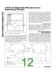
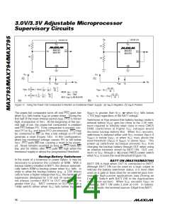
In most battery-operated portable systems, reserve
energy in the battery provides ample time to complete
the s hutd own routine onc e the low-line wa rning is
encountered and before reset asserts. If the system
CC
BATT
3.6V
MAX793
MAX794
MAX795
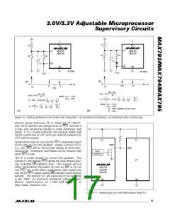
must also contend with a more rapid V fall time, such
CC
25Ω EQUIVALENT
SOURCE IMPEDANCE
as when the main battery is disconnected or a high-
side switch is opened during normal operation, use
50Ω CABLE
capacitance on the V line to provide time to execute
the shutdown routine (Figure 11).
CC
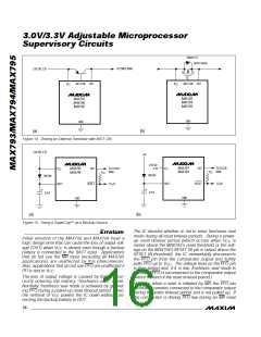
CE OUT
CE IN
50Ω
First, calculate the worst-case time required for the sys-
tem to perform its shutdown routine. Then, with the worst-
case shutdown time, the worst-case load current, and the
50pF
C *
50Ω
L
GND
minimum low-line to reset threshold (V min), calculate
LR
the amount of capacitance required to allow the shut-
down routine to complete before reset is asserted:
*C INCLUDES LOAD CAPACITANCE AND SCOPE PROBE CAPACITANCE.
L
C
> I
x t
/ V
SHDN LR
HOLD
LOAD
Figure 9. CE Propagation Delay Test Circuit
whe re I
is the c urre nt b e ing dra ine d from the
LOAD
capacitor, V is the low-line to reset threshold differ-
LR
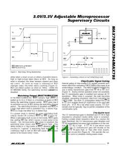
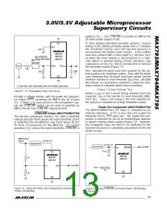
through a voltage divider, with the power-fail compara-
tor output (PFO) providing the NMI to the µP (Figure
10). If there is no easy access to the unregulated sup-
ply, the LOWLINE output can be used to generate an
NMI to the µP (see LOWLINE Output section).
ence (V - V
), and t
RST
is the time required for
LL
SHDN
the system to complete an orderly shutdown routine.
Power-Fail Comparator (MAX793/MAX794)
The MAX793/MAX794’s PFI input is compared to an
internal reference. If PFI is less than the power-fail
LOWLINE Output (MAX793/MAX794)
threshold (V ), PFO goes low. The power-fail com-
PFT
The low-line comparator monitors V
with a threshold
CC
parator is intended for use as an undervoltage detector
to signal a failing power supply (Figure 12). However,
the comparator does not need to be dedicated to this
function because it is completely separate from the rest
of the circuitry.
voltage typically 45mV above the reset threshold (10mV
of hysteresis) for the MAX793, and 15mV above RESET
IN (4mV of hysteresis) for the MAX794. For normal
operation (V above the reset threshold), LOWLINE is
CC
UNREGULATED
3.0V OR 3.3V
SUPPLY
REGULATOR
3.0V OR 3.3V
REGULATOR
TO µP NMI
LOWLINE
V
CC
C
HOLD
V
CC
MAX793
MAX794
MAX793
MAX794
R1
R2
TO µP NMI
PFO
PFI
C
> I
x t
V
LR
HOLD LOAD SHDN
GND
GND
Figure 10. Using the Power-Fail Comparator to Generate
Power-Fail Warning
Figure 11. Using LOWLINE to Provide Power-Fail Warning
to the µP
______________________________________________________________________________________ 13

 MAXIM [ MAXIM INTEGRATED PRODUCTS ]