3 .0 V/3 .3 V Ad ju s t a b le Mic ro p ro c e s s o r
S u p e rvis o ry Circ u it s
34/MAX795
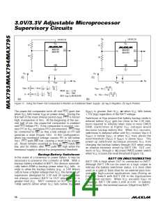
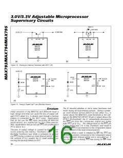
to V , the collector to OUT, and the base to BATT ON
CC
(Figure 14a). No current-limiting resistor is required,
but a resistor connecting the base of the PNP to BATT
3.3V
V
RST
ON can be used to limit the current drawn from V
prolonging battery life in portable equipment.
,
CC
V
CC
V
SW
If you are using a PMOS transistor, however, it must be
c onne c te d b a c kwa rd s from the tra d itiona l me thod .
Connect the gate to BATT ON, the drain to V , and
CC
the source to OUT (Figure 14b). This method orients
3.6V
3.6V
the body diode from V
to OUT and prevents the
3.3V
CC
backup battery from discharging through the FET when
its gate is high. Two PMOS transistors in the Siliconix
V
OUT
LITTLE FOOT™ series are specified with V down to
GS
V
BATT
= 3.6V
-2.7V. The Si9433DY has a maximum 100mΩ drain-
source on-resistance with 2.7V of gate drive and a 2A
drain-source current. The Si9434DY specifies a 60mΩ
drain-source on-resistance with 2.7V of gate drive and
a 5.1A drain-source current.
Figure 13. Battery Switchover Timing
Table 1. Input and Output Status in
Battery-Backup Mode
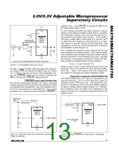
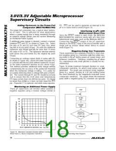
Us in g a S u p e rCa p ™ a s a Ba c k u p
P o w e r S o u rc e
PIN NAME
STATUS
Connected to BATT through an internal
Sup e rCa p s ™ a re c a p a c itors with e xtre me ly hig h
capacitance values (e.g., order of 0.47F) for their size.
Figure 15 shows two ways to use a SuperCap as a
backup power source. The SuperCap can be connect-
ed through a diode to the 3V input (Figure 15a); or, if a
5V s up p ly is a ls o a va ila b le , the Sup e rCa p c a n b e
charged up to the 5V supply (Figure 15b), allowing a
OUT
140Ω switch
V
CC
Disconnected from OUT
Pulled up to BATT
Logic low
BATT ON
BATT OK
PFI
Disabled
PFO
Logic low
longer backup period. Since V
can exceed V
BATT
CC
MR
Disabled, but still pulled up to V
while V
is above the reset threshold, there are no
CC
CC
special precautions when using these µP supervisors
with a SuperCap.
WDO
Logic low
Disabled
Logic low
WDI
RESET
RESET
BATT
Op e ra t io n w it h o u t a
Ba c k u p P o w e r S o u rc e
The s e µP s up e rvis ors we re d e s ig ne d for b a tte ry-
backed applications. If a backup battery is not used,
Pulled up to V
CC
Connected to OUT
Logic low
LOWLINE
CE IN
CE OUT
connect BATT, OUT, and V together, or use a differ-
CC
High impedance
Pulled to BATT
ent µP supervisor. See the µP Supervisory Circuits
table at the end of this data sheet.
__________Ap p lic a t io n s In fo rm a t io n
These µP supervisory circuits are not short-circuit pro-
Re p la c in g t h e Ba c k u p Ba t t e ry
The backup power source can be removed while V
CC
re ma ins va lid , without d a ng e r of trig g e ring a re s e t
pulse, provided that BATT is decoupled with a 0.1µF
tected. Shorting V
to ground, excluding power-up
OUT
transients such as charging a decoupling capacitor,
destroys the device. Decouple both V and BATT
capacitor to ground. As long as V
stays above the
CC
CC
re s e t thre s hold , b a tte ry-b a c kup mod e c a nnot b e
entered.
pins to ground by placing 0.1µF ceramic capacitors as
close to the device as possible.
Drivin g a n Ex t e rn a l S w it c h w it h BATT ON
BATT ON can be directly connected to the base of a
PNP transistor or the gate of a PMOS transistor. The
PNP connection is straightforward: connect the emitter
™ LITTLE FOOT is a trademark of Siliconix Inc.
SuperCap is a trademark of Baknor Industries.
______________________________________________________________________________________ 15

 MAXIM [ MAXIM INTEGRATED PRODUCTS ]