3 .0 V/3 .3 V Ad ju s t a b le Mic ro p ro c e s s o r
S u p e rvis o ry Circ u it s
(OPTIONAL)
Si9433DY
SILICONIX
V
RST
V
RST
3.3V
D
S
0.1µF
0.1µF
V
CC
PMOS
R1
V
CC
BATT ON OUT
CMOS
RAM
RESET IN
CE OUT
t
RP
R2
V
CC
RESET
PFO
MAX794
ADDRESS
DECODER
CE IN
A0-A15
I/O
BATT
0.1µF
3.6V
WDI
PFO STATE LATCHED,
FRESHNESS SEAL ENABLED.
WDO
MR
(EXTERNALLY HELD AT 0V)
LOWLINE
NMI
V
CC
+5V SUPPLY
FAILURE
RESET PULLED UP TO V
CC
4.7k
PFO
+5V
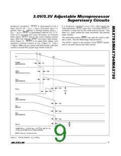
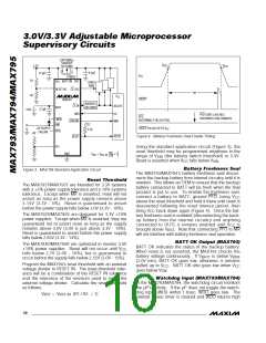
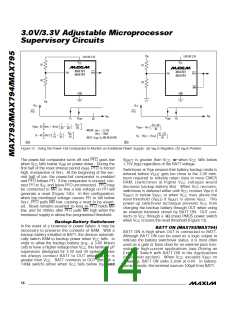
Figure 4. Battery Freshness Seal Enable Timing
RESET
RESET
PFI
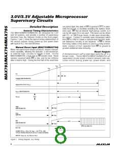
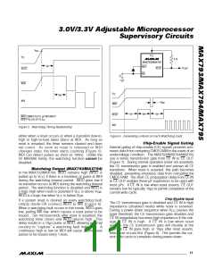
Using the standard application circuit (Figure 3), the
reset threshold may be programmed anywhere in the
R1
GND
+ 1
V
= V
RST RST IN
(
)
R2
range of V
(the battery switch threshold) to 5.5V.
SW
Reset is asserted when V falls below V
.
CC
SW
Ba t t e ry Fre s h n e s s S e a l
The MAX793/MAX794’s battery freshness seal discon-
nects the backup battery from internal circuitry until it is
needed. This allows an OEM to ensure that the backup
battery connected to BATT will be fresh when the final
product is put to use. To enable the freshness seal,
Figure 3. MAX794 Standard Application Circuit
34/MAX795
Re s e t Th re s h o ld
The MAX793T/MAX795T are intended for 3.3V systems
with a ±5% power-supply tolerance and a 10% systems
tolerance. Except when MR is asserted, reset will not
assert as long as the power supply remains above
3.15V (3.3V - 5%). Re s e t is g ua ra nte e d to a s s e rt
before the power supply falls below 3.0V (3.3V - 10%).
connect a battery to BATT, ground PFO, bring V
CC
above the reset threshold and hold it there until reset is
deasserted following the reset timeout period, then
bring V
back down again (Figure 4). Once the bat-
CC
The MAX793S/MAX795S are designed for 3.3V ±10%
power supplies. Except when MR is asserted, they are
guaranteed not to assert reset as long as the supply
remains above 3.0V (3.0V is just above 3.3V - 10%).
Reset is guaranteed to assert before the power supply
falls below 2.85V (3.3V - 14%).
tery freshness seal is enabled (disconnecting the back-
up b a tte ry from the inte rna l c irc uitry a nd a nything
connected to OUT), it remains enabled until V
is
CC
brought above V . Note that connecting PFO to MR
RST
will not interfere with battery freshness seal operation.
BATT OK Ou t p u t (MAX7 9 3 )
BATT OK indicates the status of the backup battery.
When reset is not asserted, the MAX793 checks the
The MAX793R/MAX795R are optimized to monitor 3.0V
±10% power supplies. Reset will not occur until V
CC
falls below 2.7V (3.0V - 10%), but is guaranteed to
occur before the supply falls below 2.55V (3.0V - 15%).
battery voltage continuously. If V
is below V
BATT
BOK
(2.0V min), BATT OK goes low; otherwise, it remains
pulled up to V . BATT OK also goes low when V
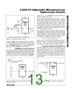
Program the MAX794’s reset threshold with an external
voltage divider to RESET IN. The reset-threshold toler-
ance will be a combination of the RESET IN tolerance
and the tolerance of the resistors used to make the
external voltage divider. Calculate the reset threshold
as follows:
CC
CC
goes below V
.
SW
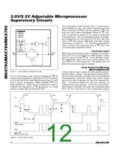
Wa t c h d o g In p u t (MAX7 9 3 /MAX7 9 4 )
In the MAX793/MAX794, the watchdog circuit monitors
the µP’s activity. If the µP does not toggle the watch-
dog input (WDI) within 1.6sec, WDO goes low. The
internal 1.6sec timer is cleared and WDO returns high
V
RST
= V
(R1 / R2 + 1)
RST IN
10 ______________________________________________________________________________________

 MAXIM [ MAXIM INTEGRATED PRODUCTS ]